Chapter 08: Light Effect
Add dynamic 2D lighting to the game
In this chapter, we are going to add a dynamic 2D lighting system to Dungeon Slime. At the end of this chapter, the game will look something like this:
| Figure 8-1: The game will have lighting |
So far, the game's rendering has been fairly straightforward. The game consists of a bunch of sprites, and all those sprites are drawn straight to the screen using a custom shader effect. Adding lights is going to complicate the rendering, because now each sprite must consider "N" number of lights before being drawn to the screen.
There are two broad categories of strategies for rendering lights in a game,
In the earlier days of computer graphics, forward rendering was ubiquitous. Imagine a simple 2D scene where there is a single sprite with 3 lights nearby. The sprite would be rendered 3 times, once for each light. Each individual pass would layer any existing passes with the next light. This technique is forward rendering, and there are many optimizations that make it fast and efficient. However, in a scene with lots of objects and lots of lights, each object needs to be rendered for each light, and the amount of rendering can scale poorly. The amount of work the renderer needs to do is roughly proportional to the number of sprites (S) multiplied by the number of lights (L), or S * L.
In the 2000's, the deferred rendering strategy was introduced and popularized by games like S.T.A.L.K.E.R. In deferred rendering, each object is drawn once without any lights to an off-screen texture. Then, each light is drawn on top of the off-screen texture. To make that possible, the initial rendering pass draws extra data about the scene into additional off-screen textures. Theoretically, a deferred renderer can handle more lights and objects because the work is roughly approximate to the sprites (S) added to the lights (L), or S + L.
Deferred rendering was popular for several years. MonoGame is an adaptation of XNA, which came out in the era of deferred rendering. However, deferred renderers are not a silver bullet for performance and graphics programming. The crux of a deferred renderer is to bake data into off-screen textures, and as monitor resolutions have gotten larger and larger, the 4k resolutions make off-screen textures more expensive than before. Also, deferred renderers cannot handle transparent materials. Many big game projects use deferred rendering for most of the scene, and a forward renderer for the final transparent components of the scene. As with all things, which type of rendering to use is a nuanced decision. There are new types of forward rendering strategies (see, clustered rendering, or forward++ rendering) that can out perform deferred renderers. However, for our use cases, the deferred rendering technique is sufficient.
If you are following along with code, here is the code from the end of the previous chapter.
Sample Source
The full source for this tuturial can be located on the 3.8.5 branch of the main MonoGame.Samples repository
As shown below:
https://github.com/MonoGame/MonoGame.Samples/tree/3.8.5/Tutorials/2dShaders
Adding Deferred Rendering
Writing a simple deferred renderer can be worked out in a few steps:
- take the scene as we are drawing it currently, and store it in an off-screen texture. This texture is often called the diffuse texture, or color texture.
- render the scene again, but instead of drawing the sprites normally, draw their Normal maps to an off-screen texture, called the normal texture.
- create yet another off-screen texture, called the light texture, where lights are layered on top of each other using the normal texture,
- finally, create a rendering to the screen based on the lighting texture and the color texture.
The second stage references a new term, called the Normal texture. We will come back to this later in the chapter. For now, we will focus on the other steps.
Tip
Texture vs Map vs Buffer
It is very common for people to refer to textures as maps or buffers in computer graphics, so if you see the terms "color map", "color texture", or "color buffer"; they very likely refer to the same thing. The terms are synonymous.
Drawing to an off-screen texture
To get started, we need to draw the main game sprites to an off-screen texture instead of directly to the screen.
Create a new file in the shared MonoGameLibrary
graphicsfolder calledDeferredRenderer.csand populate it with the following code:using Microsoft.Xna.Framework; using Microsoft.Xna.Framework.Graphics; namespace MonoGameLibrary.Graphics; public class DeferredRenderer { /// <summary> /// A texture that holds the unlit sprite drawings /// </summary> public RenderTarget2D ColorBuffer { get; set; } public DeferredRenderer() { var viewport = Core.GraphicsDevice.Viewport; ColorBuffer = new RenderTarget2D( graphicsDevice: Core.GraphicsDevice, width: viewport.Width, height: viewport.Height, mipMap: false, preferredFormat: SurfaceFormat.Color, preferredDepthFormat: DepthFormat.None); } }The
ColorBufferproperty is aRenderTarget2D, which is a special type ofTexture2Dthat MonoGame can draw into. In order for MonoGame to draw anything into theColorBuffer, it needs to be bound as the current render target. Add the following function to theDeferredRendererclass.The
SetRenderTarget()function instructs all future MonoGame draw operations to render into theColorBuffer. Add this function to theDeferredRendererclass:public void StartColorPhase() { // all future draw calls will be drawn to the color buffer Core.GraphicsDevice.SetRenderTarget(ColorBuffer); Core.GraphicsDevice.Clear(Color.Transparent); }Once all of the rendering is complete, we need to switch the primary render target back to the screen so that we can actually see anything.
Note
Set the render target to
nullto draw to the screen.RenderTargets are off-screen buffers that MonoGame can draw graphics into. If the render target isnull, then there is no off-screen buffer to use, and as such, the only place to render the graphics in this case is directly to the screen.Add the following method to the
DeferredRendererclass.public void Finish() { // all future draw calls will be drawn to the screen // note: 'null' means "the screen" in MonoGame Core.GraphicsDevice.SetRenderTarget(null); }Now we can use this new off-screen texture in the
GameScene. Add a new class member in theGameSceneof theDungeonSlimeproject:// The deferred rendering resources private DeferredRenderer _deferredRenderer;And initialize it in the
Initialize()method:// Create the deferred rendering resources _deferredRenderer = new DeferredRenderer();Then, to actually use the new off-screen texture, we need to invoke the
StartColorPhase()andFinish()methods in theDraw()method of theGameScene.Right before the
SpriteBatch.Begin()class, invoke theStartColorPhase()method. Here is theDraw()method with most of the code left out, but it demonstrates where theStartColorPhase()andFinish()methods belong:public override void Draw(GameTime gameTime) { // ... configure the sprite batch // Start rendering to the deferred renderer _deferredRenderer.StartColorPhase(); Core.SpriteBatch.Begin( samplerState: SamplerState.PointClamp, sortMode: SpriteSortMode.Immediate, rasterizerState: RasterizerState.CullNone, effect: _gameMaterial.Effect); // ... all of the actual draw code. // Always end the sprite batch when finished. Core.SpriteBatch.End(); _deferredRenderer.Finish(); // Draw the UI _ui.Draw(); }If you run the game now, once you have started a new game from the title screen, the screen will appear blank except for the UI (and you will get the game over prompt rather quickly as the game logic itself is still actually running). That is because the game is rendering to an off-screen texture, but nothing is rendering the off-screen texture back to the screen. For now, we will add some diagnostic visualization of the off-screen texture.
Add the following function to the
DeferredRendererclass.This function starts a new sprite batch and draws the
ColorBufferto the top-left corner of the screen, with an orange border around it to indicate it is a debug visualization:public void DebugDraw() { var viewportBounds = Core.GraphicsDevice.Viewport.Bounds; // the debug view for the color buffer lives in the top-left. var colorBorderRect = new Rectangle( x: viewportBounds.X, y: viewportBounds.Y, width: viewportBounds.Width / 2, height: viewportBounds.Height / 2); // shrink the color rect by 8 pixels var colorRect = colorBorderRect; colorRect.Inflate(-8, -8); Core.SpriteBatch.Begin(); // draw a debug border for the color buffer Core.SpriteBatch.Draw(Core.Pixel, colorBorderRect, Color.MonoGameOrange); // draw the color buffer Core.SpriteBatch.Draw(ColorBuffer, colorRect, Color.White); Core.SpriteBatch.End(); }And call this new method from the end of the
Draw()method ofGameScene, just after the GUM UI draws:public override void Draw(GameTime gameTime) { // ... // Draw the UI _ui.Draw(); // Render the debug view for the game _deferredRenderer.DebugDraw(); }
Now when you run the game, you should see the diffuse texture of the game that was generated in this first pass, appearing in the upper-left corner of the screen.
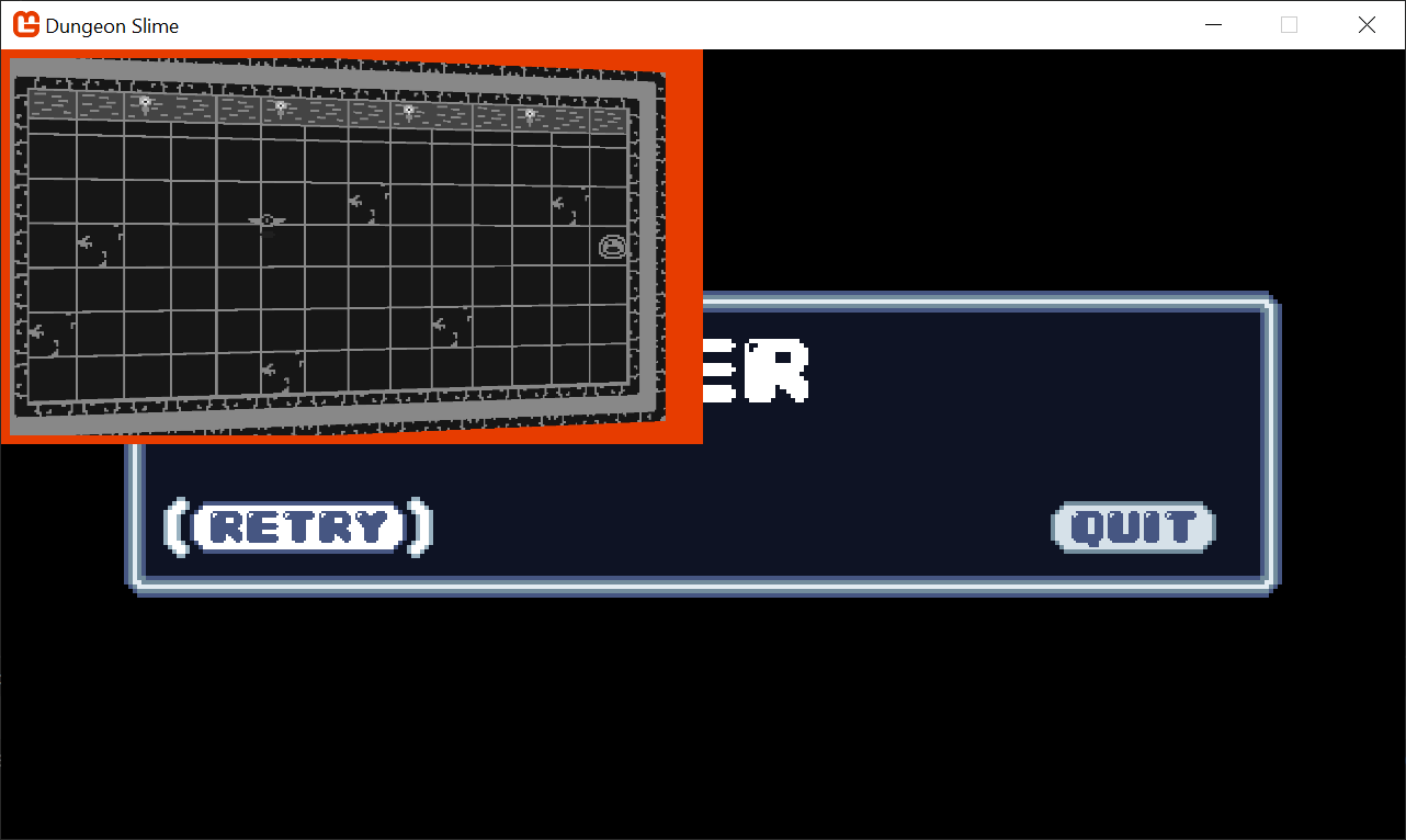 |
|---|
| Figure 8-2: The color buffer debug view |
Note
If you want to clear up all the other Debug windows for the previous effects, feel free to go through the LoadContent methods in each of the classes and either set Material.IsDebugVisible = false; or just remove those lines.
Setting up the Light Buffer
The next step is to create some lights and render them to a second off-screen texture.
To start, add a second
RenderTarget2Dproperty to theDeferredRendererclass:/// <summary> /// A texture that holds the drawn lights /// </summary> public RenderTarget2D LightBuffer { get; set; }And initialize it in the constructor exactly the same as the
ColorBufferwas initialized:public DeferredRenderer() { // ... LightBuffer = new RenderTarget2D( graphicsDevice: Core.GraphicsDevice, width: viewport.Width, height: viewport.Height, mipMap: false, preferredFormat: SurfaceFormat.Color, preferredDepthFormat: DepthFormat.None); }We need to add another method to switch MonoGame into drawing sprites onto the new off-screen texture:
public void StartLightPhase()
{
    // all future draw calls will be drawn to the light buffer
    Core.GraphicsDevice.SetRenderTarget(LightBuffer);
    Core.GraphicsDevice.Clear(Color.Black);
}
Then, we need to call the new method in the
GameScene'sDraw()method between the currentSpriteBatch.End()call and thedeferredRenderer.Finish()call:public override void Draw(GameTime gameTime) { // ... // Always end the sprite batch when finished. Core.SpriteBatch.End(); // start rendering the lights _deferredRenderer.StartLightPhase(); // TODO: draw lights // finish the deferred rendering _deferredRenderer.Finish(); // ... }To finish off with the light implementation changes for now, add the
LightBufferto theDebugDraw()view ofDeferredRendereras well:public void DebugDraw() { var viewportBounds = Core.GraphicsDevice.Viewport.Bounds; // the debug view for the color buffer lives in the top-left. var colorBorderRect = new Rectangle( x: viewportBounds.X, y: viewportBounds.Y, width: viewportBounds.Width / 2, height: viewportBounds.Height / 2); // shrink the color rect by 8 pixels var colorRect = colorBorderRect; colorRect.Inflate(-8, -8); // the debug view for the light buffer lives in the top-right. var lightBorderRect = new Rectangle( x: viewportBounds.Width / 2, y: viewportBounds.Y, width: viewportBounds.Width / 2, height: viewportBounds.Height / 2); // shrink the light rect by 8 pixels var lightRect = lightBorderRect; lightRect.Inflate(-8, -8); Core.SpriteBatch.Begin(); // draw a debug border for the color buffer Core.SpriteBatch.Draw(Core.Pixel, colorBorderRect, Color.MonoGameOrange); // draw the color buffer Core.SpriteBatch.Draw(ColorBuffer, colorRect, Color.White); // draw a debug border for the light buffer Core.SpriteBatch.Draw(Core.Pixel, lightBorderRect, Color.CornflowerBlue); // draw the light buffer Core.SpriteBatch.Draw(LightBuffer, lightRect, Color.White); Core.SpriteBatch.End(); }
Now when you run the game, you will see a blank texture in the top-right. It is blank because there are no lights yet.
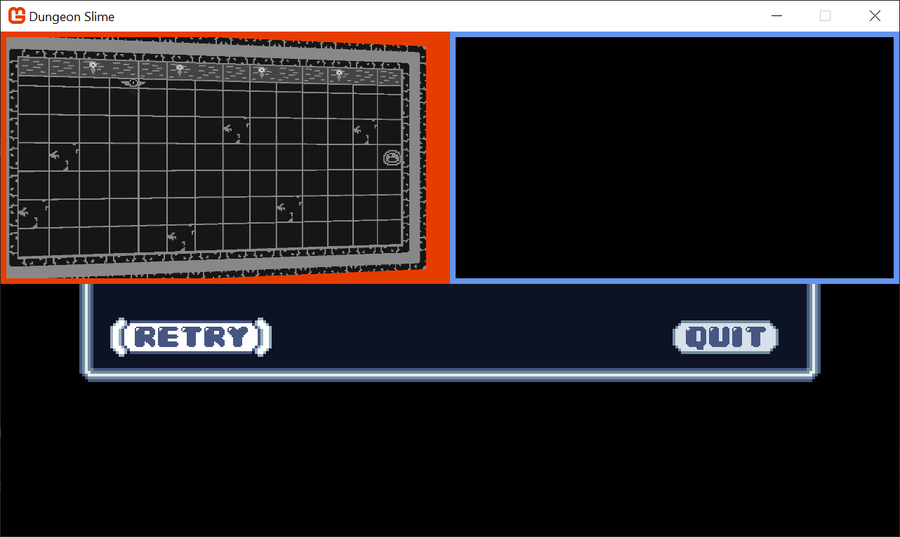 |
|---|
| Figure 8-3: A blank light buffer |
Point Light Shader
Each light will be drawn using a shader so that the fall-off and intensity can be adjusted in real time.
Use the
mgcb-editorto create a new Sprite Effect calledpointLightEffectin the SharedContenteffectsfolder of theMonoGameLibraryproject. For now, leave it as the default shader. Remember, save before exiting the MGCB editor.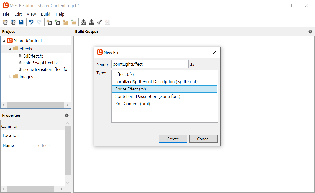
Figure 8-4: Adding a point light effect shader We need to load the new
pointLightEffectin theCoreclass. First, create a new class member in theCoreclass of theMonoGameLibraryproject:/// <summary> /// The material that draws point lights /// </summary> public static Material PointLightMaterial { get; private set; }And then load the
Materialin theLoadContent()method:protected override void LoadContent() { base.LoadContent(); // ... PointLightMaterial = SharedContent.WatchMaterial("effects/pointLightEffect"); PointLightMaterial.IsDebugVisible = true; }And do not forget to enable the hot-reload by adding the
Update()line in theUpdate()method:protected override void Update(GameTime gameTime) { // ... PointLightMaterial.Update(); // ... }In order to handle multiple lights, it will also be helpful to have a class that represents each light. Create a new file in the MonoGameLibrary's graphics folder called
PointLight.csand populate it with the following:using System.Collections.Generic; using Microsoft.Xna.Framework; using Microsoft.Xna.Framework.Graphics; namespace MonoGameLibrary.Graphics; public class PointLight { /// <summary> /// The position of the light in world space /// </summary> public Vector2 Position { get; set; } /// <summary> /// The color tint of the light /// </summary> public Color Color { get; set; } = Color.White; /// <summary> /// The radius of the light in pixels /// </summary> public int Radius { get; set; } = 250; }Back to the
GameSceneclass in theDungeonSlimeproject, create aList<PointLight>as a new property:// A list of point lights to be rendered private List<PointLight> _lights = new List<PointLight>();In order to start building intuition for the point light shader, we will need a debug light to experiment with. Add this snippet to the
Initialize()method:public override void Initialize() { // ... _lights.Add(new PointLight { Position = new Vector2(300, 300) }); }Next, we need to draw the
PointLightlist using the newPointLightMaterial. Add the following function to thePointLightclass:public static void Draw(SpriteBatch spriteBatch, List<PointLight> pointLights) { spriteBatch.Begin( effect: Core.PointLightMaterial.Effect ); foreach (var light in pointLights) { var diameter = light.Radius * 2; var rect = new Rectangle((int)(light.Position.X - light.Radius), (int)(light.Position.Y - light.Radius), diameter, diameter); spriteBatch.Draw(Core.Pixel, rect, light.Color); } spriteBatch.End(); }And back in
GameScene, call it from theDraw()method, after theStartLightPhase()invocation:public override void Draw(GameTime gameTime) { // ... // start rendering the lights _deferredRenderer.StartLightPhase(); PointLight.Draw(Core.SpriteBatch, _lights); // ... }
Now when you run the game, you will see a blank white square where the point light is located (at 300,300).
Note
Sorry for all the jumping back and forth between classes in this chapter, but it was critical to help you understand the flow of the lighting, which is critical with any deferred rendering pattern.
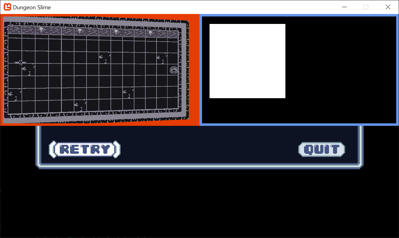 |
|---|
| Figure 8-5: The light buffer with a square |
The next task is to write the pointLightEffect.fx shader file so that the white square looks more like a point light. There are several ways to create the effect, some more realistic than others. For DungeonSlime, a realistic light falloff is not going to look great, so we will develop something custom.
To start, open the
pointLightEffect.fxshader in theMonoGameLibrarySharedContent/effects folder and replace theMainPSfunction with the following, which calculates the distance from the center of the image and renders it to the red-channel:float4 MainPS(VertexShaderOutput input) : COLOR { float dist = length(input.TextureCoordinates - .5); return float4(dist, 0, 0, 1); }Note
For the sake of clarity, these screenshots show only the
LightBufferas full screen, that way we can focus on the distance based return value.If you want to do that too, change the
DebugDraw()method to use the entire viewport for thelightBorderRect, like this:public void DebugDraw() { // ... // the debug view for the light buffer lives in the top-right. // var lightBorderRect = new Rectangle( // x: viewportBounds.Width / 2, // y: viewportBounds.Y, // width: viewportBounds.Width / 2, // height: viewportBounds.Height / 2); var lightBorderRect = viewportBounds; // TODO: remove this; it makes the light rect take up the whole screen. // ... }Just do not forget to revert this change later!
Tip
Add a pause mechanic!
It can be really hard to debug the graphics stuff while the game is being played. Earlier in the series, we just added an early-return in the
GameScene'sUpdate()method. We could do that again, or we could add a debug key to pause the game. Add a class variable called_debugPause:private bool _debugPause = false;And then add this snippet to the top of the
Update()method:if (Core.Input.Keyboard.WasKeyJustPressed(Keys.P)) { _debugPause = !_debugPause; } if (_debugPause) return;And do not forget to add the
usingstatement:using Microsoft.Xna.Framework.Input;Now you will be able to hit the
pkey to pause the game without showing the menu. Remember to take this out before shipping your game!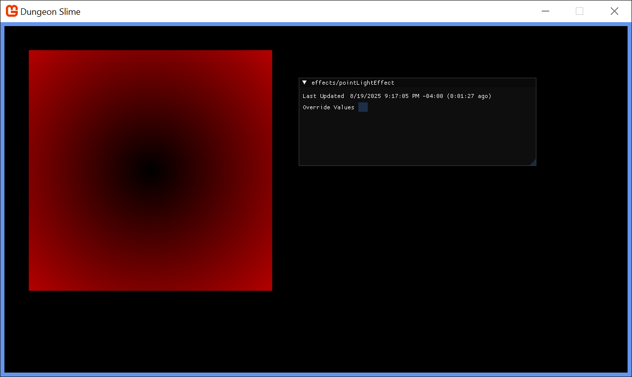
Figure 8-6: Showing the distance from the center of the light in the red channel Note
Remember, you can leave the project running now, while we implement these effect changes to see it in realtime.
This is starting to look like a light, but in reverse. Create a new variable,
falloffwhich inverts the distance. Thesaturatefunction is shorthand for clamping the value between0and1:float4 MainPS(VertexShaderOutput input) : COLOR { float dist = length(input.TextureCoordinates - .5); float falloff = saturate(.5 - dist); return float4(falloff, 0, 0, 1); }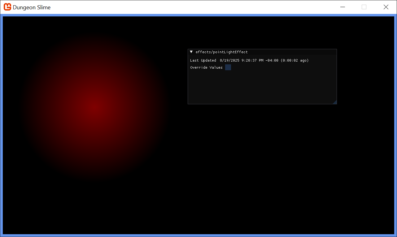
Figure 8-7: Invert the distance That looks more light-like. Now it is time to add some artistic control parameters to the shader. First, it would be good to be able to increase the brightness of the light. Multiplying the
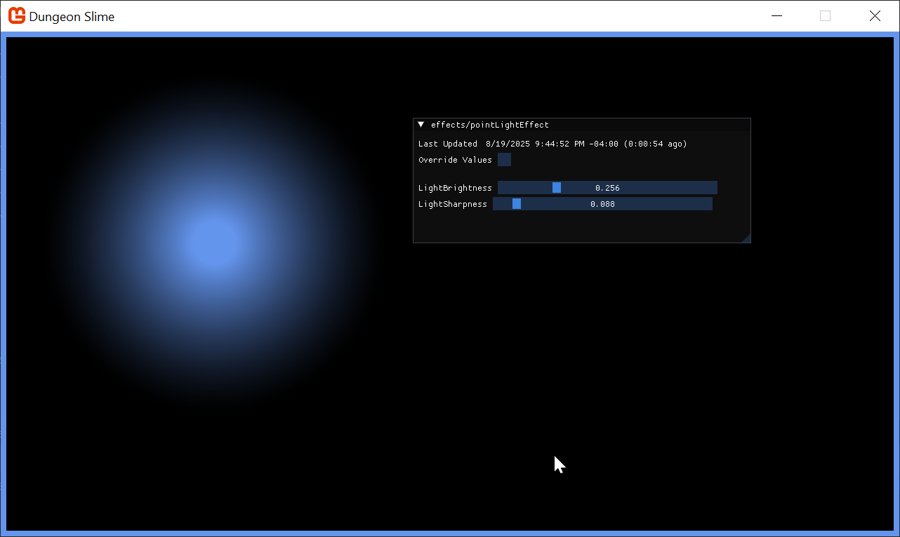
falloffby some number larger than 1 would increase the brightness, but leave the unlit sections completely unlit:float LightBrightness; float4 MainPS(VertexShaderOutput input) : COLOR { float dist = length(input.TextureCoordinates - .5); float falloff = saturate(.5 - dist) * (LightBrightness + 1); return float4(falloff, 0, 0, 1); }Figure 8-8: A LightBrightness parameter It would also be good to control the sharpness of the falloff. The
pow()function raises thefalloffto some exponent value:float LightBrightness; float LightSharpness; float4 MainPS(VertexShaderOutput input) : COLOR { float dist = length(input.TextureCoordinates - .5); float falloff = saturate(.5 - dist) * (LightBrightness + 1); falloff = pow(falloff, LightSharpness + 1); return float4(falloff, 0, 0, 1); }Figure 8-9: A LightSharpness parameter Finally, the shader parameters currently range from
0to1, but it would be nice to push the brightness and sharpness beyond1. Add an additionalrangemultiplier in the shader code:float LightBrightness; float LightSharpness; float4 MainPS(VertexShaderOutput input) : COLOR { float dist = length(input.TextureCoordinates - .5); float range = 5; // arbitrary maximum. float falloff = saturate(.5 - dist) * (LightBrightness * range + 1); falloff = pow(abs(falloff), LightSharpness * range + 1); return float4(falloff, 0, 0, 1); }Figure 8-10: Increase the range of the artistic parameters The final touch is to return the
Colorof the light, instead of just the red debug value. Theinput.Colorcarries theColorpassed through theSpriteBatch, so we can use that. We can also multiply the alpha channel of the color by thefalloffto fade the light out without changing the light color itself:float LightBrightness; float LightSharpness; float4 MainPS(VertexShaderOutput input) : COLOR { float dist = length(input.TextureCoordinates - .5); float range = 5; // arbitrary maximum. float falloff = saturate(.5 - dist) * (LightBrightness * range + 1); falloff = pow(abs(falloff), LightSharpness * range + 1); float4 color = input.Color; color.a = falloff; return color; }Warning
Wait, the light broke! If you run the project at this state, the light seems to revert back to a fully opaque square! That is because of the
blendStateof theSpriteBatch. Even though thea(or alpha) channel of the color in the shader is being set to a nicefalloff, the defaultblendStatesees any positive alpha as "fully opaque". We are going to fix this right away!And change the
blendStateof the light'sSpriteBatchdraw call in thePointLightclass to additive for effect:public static void Draw(SpriteBatch spriteBatch, List<PointLight> pointLights, Texture2D normalBuffer) { spriteBatch.Begin( effect: Core.PointLightMaterial.Effect, blendState: BlendState.Additive ); // ... }In the
GameScenewe can replace the initialization of the light to change its color in C# toCornflowerBluein theInitializemethod:_lights.Add(new PointLight { Position = new Vector2(300,300), Color = Color.CornflowerBlue });Finally, in the
CoreclassLoadContentmethod, set the default shader parameter values for brightness and sharpness to something you like:protected override void LoadContent() { // ... PointLightMaterial = SharedContent.WatchMaterial("effects/pointLightEffect"); PointLightMaterial.IsDebugVisible = true; PointLightMaterial.SetParameter("LightBrightness", .25f); PointLightMaterial.SetParameter("LightSharpness", .1f); }
 |
|---|
| Figure 8-11: The point light in the light buffer |
The light looks good! When we revert the full-screen LightBuffer and render the LightBuffer next to the ColorBuffer, a graphical bug will become clear. The world in the ColorBuffer is rotating with the vertex shader from the previous chapter, but the LightBuffer does not have the same effect, so the light appears broken. We will fix this later on in the chapter. But for now, we are going to accept this visual glitch for the next few sections.
Note
You will need to restart your project to see the light color change, because we have only configured the hot-reload to watch for "Shader" changes. Changing the source is effectively ignored at the moment.
Combining Light and Color
Now that the light and color buffers are being drawn to separate off screen textures, we need to composite them to create the final screen render.
Create a new Sprite Effect in the
SharedContentfolder of theMonoGameLibraryproject calleddeferredCompositeEffectin the MGCB editor.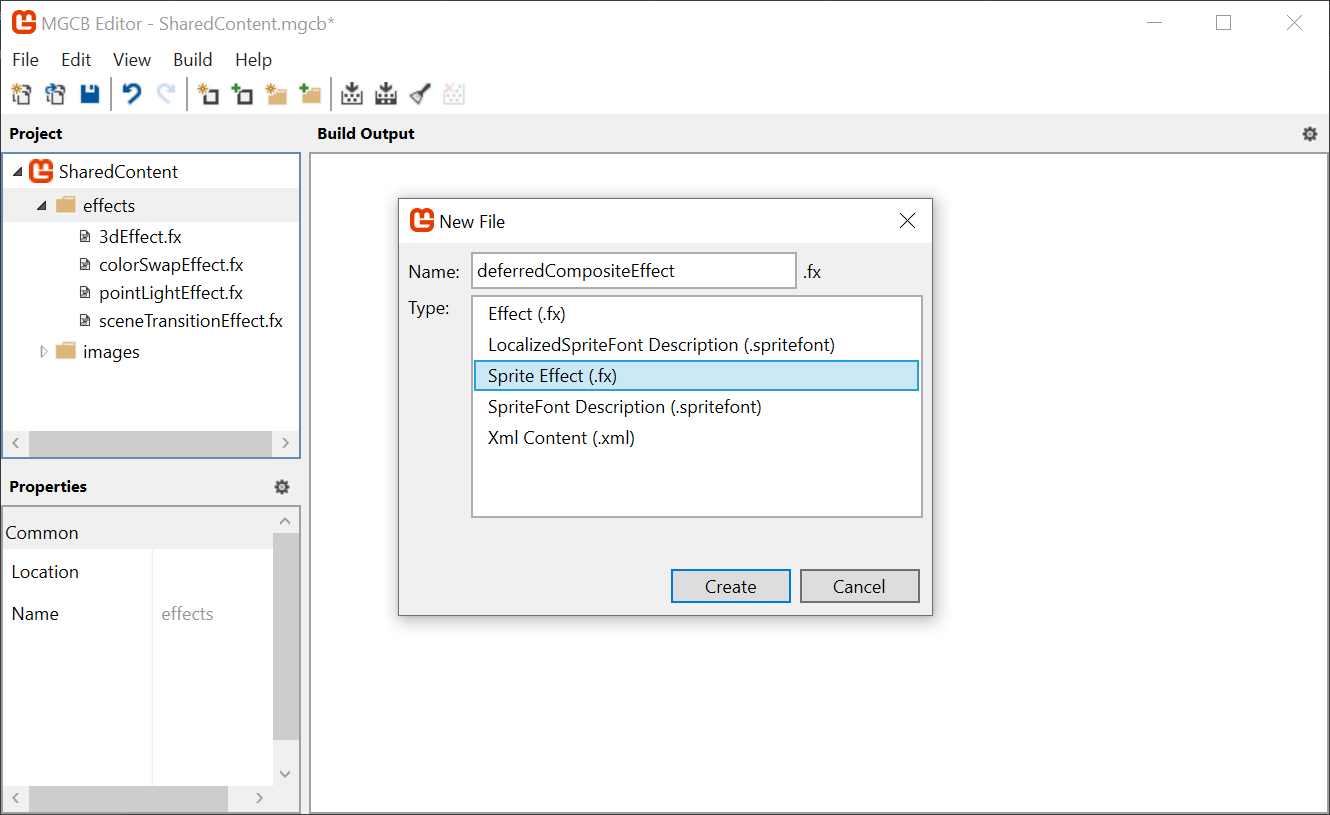
Figure 8-12: Adding the deferredCompositeEffectOpen the
Core.csclass so we can add the new shader to the pipeline, add a new property to hold the material:/// <summary> /// The material that combines the various off screen textures /// </summary> public static Material DeferredCompositeMaterial { get; private set; }Then load the effect in the
LoadContent()method:protected override void LoadContent() { // ... DeferredCompositeMaterial = SharedContent.WatchMaterial("effects/deferredCompositeEffect"); DeferredCompositeMaterial.IsDebugVisible = true; }To enable hot-reload support, also add the
Update()method:protected override void Update(GameTime gameTime) { // ... DeferredCompositeMaterial.Update(); base.Update(gameTime); }Next, create a new method in the
DeferredRendererclass that will draw the composited image:public void DrawComposite() { var viewportBounds = Core.GraphicsDevice.Viewport.Bounds; Core.SpriteBatch.Begin( effect: Core.DeferredCompositeMaterial.Effect ); Core.SpriteBatch.Draw(ColorBuffer, viewportBounds, Color.White); Core.SpriteBatch.End(); }And instead of calling the
DebugDraw()from theGameScene, call the new method before the GUM UI is drawn:public override void Draw(GameTime gameTime) { // ... _deferredRenderer.Finish(); _deferredRenderer.DrawComposite(); // Draw the UI _ui.Draw(); }If you run the game now, it will appear as it did when we started the chapter! Now it is time to factor in the
LightBuffer. ThedeferredCompositeEffectshader needs to get theLightBufferand multiply it with theColorBuffer. TheColorBufferis being passed in as the main sprite fromSpriteBatch, so we will need to add a second texture and sampler to the shader to get theLightBuffer.Open the new
deferredCompositeEffect.fxshader and add the following property:Texture2D LightBuffer; sampler2D LightBufferSampler = sampler_state { Texture = <LightBuffer>; };The main pixel function for the shader reads both the color and light values and returns their product, replace the
MainPSfunction with the following:float4 MainPS(VertexShaderOutput input) : COLOR { float4 color = tex2D(SpriteTextureSampler,input.TextureCoordinates) * input.Color; float4 light = tex2D(LightBufferSampler,input.TextureCoordinates) * input.Color; return color * light; }Note
If you see errors or red squiggles at this point, it means you likely created an
Effect(3D shader) instead of aSprite Effect(2D shader). Just delete it and recreate it, or copy the shader from the sample. It is an easy mistake to make.Back in the
DeferredRendererclass, in theDrawCompositefunction before the sprite batch starts, make sure to pass theLightBufferto the material:public void DrawComposite() { Core.DeferredCompositeMaterial.SetParameter("LightBuffer", LightBuffer); var viewportBounds = Core.GraphicsDevice.Viewport.Bounds; Core.SpriteBatch.Begin( effect: Core.DeferredCompositeMaterial.Effect ); Core.SpriteBatch.Draw(ColorBuffer, viewportBounds, Color.White); Core.SpriteBatch.End(); }The light is working! However, the whole scene is too dark to see what is going on or play the game.
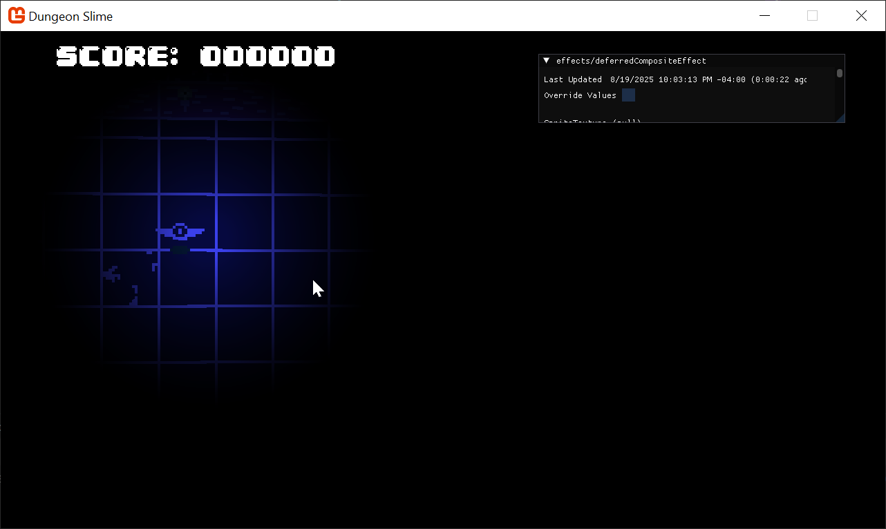
Figure 8-13: The light and color composited To solve this, we can add a small amount of ambient light to the
deferredCompositeEffectshader:float AmbientLight; float4 MainPS(VertexShaderOutput input) : COLOR { float4 color = tex2D(SpriteTextureSampler,input.TextureCoordinates) * input.Color; float4 light = tex2D(LightBufferSampler,input.TextureCoordinates) * input.Color; light = saturate(light + AmbientLight); return color * light; }Figure 8-14: Adding ambient light Find a value of ambient that you like and then set the parameter from code in the
DrawCompositemethod of theDeferredRenderer:public void DrawComposite(float ambient=.4f) { Core.DeferredCompositeMaterial.SetParameter("AmbientLight", ambient); // ... }Figure 8-15: A constant ambient value Warning
The light is not moving with the rest of the game as the world rotates around the camera. It does not look too bad because the light effect is just being applied statically over the top of the screen. We are going to fix this soon.
Normal Textures
The lighting is working, but it still feels a bit flat. Ultimately, the light is being applied to our flat 2D sprites uniformly, so the sprites do not feel like they have any depth. Normal mapping is a technique designed to help make flat surfaces appear 3D by changing how much the lighting affects each pixel depending on the "Normal" of the surface at the given pixel.
Normal textures encode the direction (also called the normal) of the surface at each pixel. The direction of the surface is a 3D vector where the x component lives in the red channel, the y component lives in the green channel, and the z component lives in the blue channel. The directions are encoded as colors, so each component can only range from 0 to 1. The direction vector components need to range from -1 to 1, so a color channel value of .5 results in a 0 value for the direction vector.
Note
If you want to learn more about the foundations of normal mapping, check out this article on Normal Mapping from LearnOpenGL.com
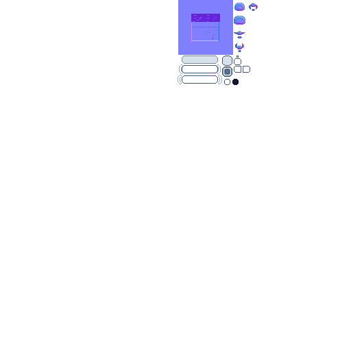
Generating normal maps is an art form. Generally, you find a normal map picker, similar to a color wheel, and paint the directions on top of your existing artwork. This page on open game art has a free normal map wheel that shows the colors for various directions along a low-resolution sphere.
 |
|---|
| Figure 8-16: A normal picker wheel |
For this effect to work, we need an extra texture for every frame of every sprite we are drawing in the game. Given that the textures are currently coming from an atlas, the easiest thing to do will be to create a second texture that shares the same layout as the first, but uses normal data instead.
For reference, the existing texture atlas is on the left, and a version of the atlas with normal maps is on the right.
 |
 |
|---|---|
| Figure 8-17: The existing texture atlas | Figure 8-18: The normal texture atlas |
Warning
This is not the most efficient way to integrate normal maps into your game, because now there are two texture atlases. Another approach would be to add the normal maps to existing sprite atlas, and modify the Sprite code to have two regions. That is an exercise for the reader.
Download the atlas-normal.png texture, add it to the DungeonSlime's Content/Images folder and include it in the MGCB content file.
Now that we have the art assets, it is time to work the normal maps into the code.
Every time one of the game sprites is being drawn, we need to draw the corresponding normal texture information to yet another off-screen texture, called the
NormalBuffer.Start by adding a new
RenderTarget2Dto theDeferredRendererclass:/// <summary> /// A texture that holds the normal sprite drawings /// </summary> public RenderTarget2D NormalBuffer { get; set; }And initialize it in the
DeferredRenderer's constructor:public DeferredRenderer() { // ... NormalBuffer = new RenderTarget2D( graphicsDevice: Core.GraphicsDevice, width: viewport.Width, height: viewport.Height, mipMap: false, preferredFormat: SurfaceFormat.Color, preferredDepthFormat: DepthFormat.None); }So far in the series, all of the pixel shaders have returned a single
float4with theCOLORsemantic. MonoGame supports Multiple Render Targets by having a shader return astructwith multiple fields each with a uniqueCOLORsemantic.Add the following
structto thegameEffect.fxfile in theDungeonSlimeprojects Content folder:struct PixelShaderOutput { float4 color: COLOR0; float4 normal: COLOR1; };At the moment, the
gameEffect.fxis just registering theColorSwapPSfunction as the pixel function, but we will need to extend the logic to support the normal values.Create a new function in the file that will act as the new pixel shader function:
PixelShaderOutput MainPS(VertexShaderOutput input)
{
    PixelShaderOutput output;
    output.color = ColorSwapPS(input);
    output.normal = float4(1, 0, 0, 1); // for now, hard-code the normal to be red.
    return output;
}
And do not forget to update the
techniqueto reference the newMainPSfunction:technique SpriteDrawing { pass P0 { VertexShader = compile VS_SHADERMODEL MainVS(); PixelShader = compile PS_SHADERMODEL MainPS(); } };In C#, when the
GraphicsDevice.SetRenderTarget()function is called, it sets the texture that theCOLOR0semantic will be sent to. However, there is an overload calledSetRenderTargets()that accepts multipleRenderTarget2Ds, and each additional texture will be assigned to the nextCOLORsemantic.Replace the
StartColorPhase()function in theDeferredRendererwith the following:public void StartColorPhase() { // all future draw calls will be drawn to the color buffer and normal buffer Core.GraphicsDevice.SetRenderTargets(new RenderTargetBinding[] { // gets the results from shader semantic COLOR0 new RenderTargetBinding(ColorBuffer), // gets the results from shader semantic COLOR1 new RenderTargetBinding(NormalBuffer) }); Core.GraphicsDevice.Clear(Color.Transparent); }Note
The
ColorBufferandNormalBufferare grouped together and often called the Geometry-Buffer (G-Buffer). In other deferred renderers, there is even more information stored in the G-Buffer as additional textures, such as depth information, material information, or game specific data.To visualize the
NormalBuffer, we will update theDebugDraw()method by adding the elements shown below in-between the existing code.The
NormalBufferwill be rendered in the lower-left corner of the screen:public void DebugDraw() { var viewportBounds = Core.GraphicsDevice.Viewport.Bounds; // the debug view for the color buffer lives in the top-left. var colorBorderRect = new Rectangle( x: viewportBounds.X, y: viewportBounds.Y, width: viewportBounds.Width / 2, height: viewportBounds.Height / 2); // shrink the color rect by 8 pixels var colorRect = colorBorderRect; colorRect.Inflate(-8, -8); // the debug view for the light buffer lives in the top-right. var lightBorderRect = new Rectangle( x: viewportBounds.Width / 2, y: viewportBounds.Y, width: viewportBounds.Width / 2, height: viewportBounds.Height / 2); // shrink the light rect by 8 pixels var lightRect = lightBorderRect; lightRect.Inflate(-8, -8); // the debug view for the normal buffer lives in the bottom-left. var normalBorderRect = new Rectangle( x: viewportBounds.X, y: viewportBounds.Height / 2, width: viewportBounds.Width / 2, height: viewportBounds.Height / 2); // shrink the normal rect by 8 pixels var normalRect = normalBorderRect; normalRect.Inflate(-8, -8); Core.SpriteBatch.Begin(); // draw a debug border for the color buffer Core.SpriteBatch.Draw(Core.Pixel, colorBorderRect, Color.MonoGameOrange); // draw the color buffer Core.SpriteBatch.Draw(ColorBuffer, colorRect, Color.White); // draw a debug border for the light buffer Core.SpriteBatch.Draw(Core.Pixel, lightBorderRect, Color.CornflowerBlue); // draw the light buffer Core.SpriteBatch.Draw(LightBuffer, lightRect, Color.White); // draw a debug border for the normal buffer Core.SpriteBatch.Draw(Core.Pixel, normalBorderRect, Color.MintCream); // draw the normal buffer Core.SpriteBatch.Draw(NormalBuffer, normalRect, Color.White); Core.SpriteBatch.End(); }Do not forget to restore the call to the
DebugDraw()method at the end of theGameScene'sDraw()method (_deferredRenderer.DebugDraw();). You will see a completelyredNormalBuffer, because the shader is hard coding the value tofloat4(1,0,0,1).
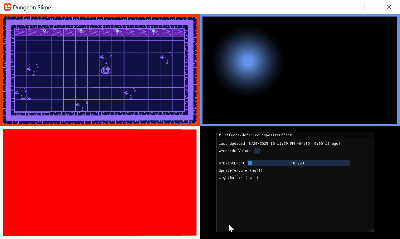 |
|---|
| Figure 8-19: A blank normal buffer |
To start rendering the normal values themselves, we need to load the normal texture into the GameScene and pass it along to the gameEffect.fx effect.
First, in the
GameSceneclass, create a newTexture2Dproperty:// The normal texture atlas private Texture2D _normalAtlas;Then load the texture in the
LoadContent()method and pass it to the_gameEffectmaterial as a parameter:public override void LoadContent() { // ... // Load the normal maps _normalAtlas = Content.Load<Texture2D>("images/atlas-normal"); _gameMaterial = Content.WatchMaterial("effects/gameEffect"); _gameMaterial.IsDebugVisible = false; _gameMaterial.SetParameter("ColorMap", _colorMap); _camera = new SpriteCamera3d(); _gameMaterial.SetParameter("MatrixTransform", _camera.CalculateMatrixTransform()); _gameMaterial.SetParameter("ScreenSize", new Vector2(Core.GraphicsDevice.Viewport.Width, Core.GraphicsDevice.Viewport.Height)); _gameMaterial.SetParameter("NormalMap", _normalAtlas); }The
GameEffectshader needs to expose aTexture2DandSamplerstate for the new normal texture, so add the following property to the shader:Texture2D NormalMap; sampler2D NormalMapSampler = sampler_state { Texture = <NormalMap>; };And then finally the
MainPSshader function needs to be updated to read theNormalMapdata for the current pixel:PixelShaderOutput MainPS(VertexShaderOutput input) { PixelShaderOutput output; output.color = ColorSwapPS(input); // read the normal data from the NormalMap float4 normal = tex2D(NormalMapSampler,input.TextureCoordinates); output.normal = normal; return output; }Now the
NormalBufferis being populated with the normal data for each sprite.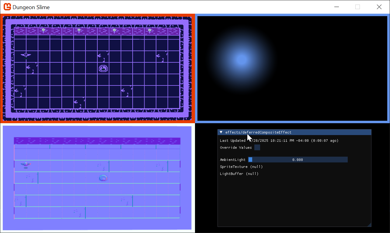
Figure 8-20: The normal map
Combining Normals with Lights
When each individual light is drawn into the LightBuffer, it needs to use the NormalBuffer information to modify the amount of light being drawn at each pixel. To set up, the PointLightMaterial is going to need access to the NormalBuffer.
Starting with the
PointLightclass in theMonoGameLibraryproject, update theDraw()method to take in theNormalMapas aTexture2D, and set it as a parameter on thePointLightMaterial:public static void Draw(SpriteBatch spriteBatch, List<PointLight> pointLights, Texture2D normalBuffer) { Core.PointLightMaterial.SetParameter("NormalBuffer", normalBuffer); // ... }And then to pass the
NormalBuffer, modify theGameScene'sDraw()method to pass the buffer:public override void Draw(GameTime gameTime) { // ... // start rendering the lights _deferredRenderer.StartLightPhase(); PointLight.Draw(Core.SpriteBatch, _lights, _deferredRenderer.NormalBuffer); // ... }The
pointLightEffect.fxshader also needs to accept theNormalBufferas a newTexture2DandSampler:Texture2D NormalBuffer; sampler2D NormalBufferSampler = sampler_state { Texture = <NormalBuffer>; };The challenge here is to find the normal value of the pixel that the light is currently shading in the pixel shader. However, the shader's
uvcoordinate space is relative to the light itself. TheNormalBufferis relative to the entire screen, not the light.We need to be able to convert the light's
uvcoordinate space into screen space, which can be done in a custom vertex shader. The vertex shader's job is to convert the world space into clip space, which in a 2D game like Dungeon Slime, essentially is screen space. We need a way to calculate the screen coordinate for each pixel being drawn for thepointLightEffectpixel shader. To achieve this, we are going to send the output from the projection matrix multiplication from the vertex shader to the pixel shader. Then, the pixel shader can convert the result into a screen space coordinateIn order to override the vertex shader function, we will need to repeat the
MatrixTransformwork from the previous chapter. However, it would be better to re-use the work from the previous chapter so that the lights also tilt and respond to theMatrixTransformthat the rest of the game world uses.Add a reference to the
3dEffect.fxhfile in thepointLightEffect.fxshader:#include "3dEffect.fxh"We need to extend the vertex function and add the extra field.
Create a new struct in the
pointLightEffect.fxfile, replacing the oldVertexShaderOutputstruct, which includes an additional parameter to accept the screen coordinates(as shown below):struct LightVertexShaderOutput { float4 Position : SV_POSITION; float4 Color : COLOR0; float2 TextureCoordinates : TEXCOORD0; float3 ScreenData : TEXCOORD1; };Next, create a new vertex function that uses the new
LightVertexShaderOutput. This function will call to the existingMainVSfunction that does the 3D effect, and add the screen coordinates afterwards:LightVertexShaderOutput LightVS(VertexShaderInput input) { LightVertexShaderOutput output; VertexShaderOutput mainVsOutput = MainVS(input); // forward along the existing values from the MainVS's output output.Position = mainVsOutput.Position;// / mainVsOutput.Position.w; output.Color = mainVsOutput.Color; output.TextureCoordinates = mainVsOutput.TextureCoordinates; // pack the required position variables, x, y, and w, into the ScreenData output.ScreenData.xy = output.Position.xy; output.ScreenData.z = output.Position.w; return output; }Note
Why are we using the
wcomponent?Long story short, when we output the
.Position, it is a 4 dimensional vector so it includes the understandablex,y, andzcomponents of the position... But it also includes a 4th component,w. Thewcomponent is used by the graphics pipeline between the vertex shader and the pixel shader to handle perspective correction. There is a lot of math to dig into, but the core issue at play is how the graphics pipeline delivers interpolated values to your pixel shader at every pixel between all of the vertices being rendered. We are not going to cover the mathematics here, but please read about homogenous coordinates and perspective divide.If you like to learn from videos, then this video by Acerola is a great exploration of the topic as well. At first the video is about simulating Playstation 1 graphics, but later, the video discusses how the interpolation between graphics stages can cause strange visual artifacts.
We need the
wcomponent because the graphics pipeline is not going to automatically perform the perspective divide correctly in this case, so we will need to re-create it ourselves later in the pixel shader. And to do that, we will need thewcomponent value.Make sure to update the
techniqueto use the new vertex function:technique SpriteDrawing { pass P0 { VertexShader = compile VS_SHADERMODEL LightVS(); PixelShader = compile PS_SHADERMODEL MainPS(); } };In the pixel function, to visualize the screen coordinates, we will short-circuit the existing light code and just render out the screen coordinates by replacing the
MainPSfunction of thepointLightEffect.fxshader with one that accepts the newLightVertexShaderOutputstruct, and make the function immediately calculate and return the screen coordinates in the red and green channel:Note
Remember, the
.ScreenData.xycarries a coordinate in clip space. However, the graphics card did not receive it in aPOSITIONsemantic, so it did not automatically normalize the values by thewchannel. Therefore, we need to do that ourselves. The range of clip space is from-1to1, so we need to convert it back to normalized0to1coordinates.float4 MainPS(LightVertexShaderOutput input) : COLOR { // correct the perspective divide. input.ScreenData /= input.ScreenData.z; // put the clip-space coordinates into screen space. float2 screenCoords = .5*(input.ScreenData.xy + 1); screenCoords.y = 1 - screenCoords.y; return float4(screenCoords, 0, 1); }Be careful, if you run the game now, it will not look right as we need to make sure to send the
MatrixTransformparameter from C# as well. TheScreenSizeparameter needs to be set for the effect in theUpdatemethod of theGameSceneclass to pass theMatrixTransformto both the_gameMaterialand theCore.PointLightMaterial.In the
GameSceneclass, replace the following in theUpdatemethod as described:// _gameMaterial.SetParameter("MatrixTransform", _camera.CalculateMatrixTransform()); <- Replace this line with: var matrixTransform = _camera.CalculateMatrixTransform(); _gameMaterial.SetParameter("MatrixTransform", matrixTransform); Core.PointLightMaterial.SetParameter("MatrixTransform", matrixTransform); Core.PointLightMaterial.SetParameter("ScreenSize", new Vector2(Core.GraphicsDevice.Viewport.Width, Core.GraphicsDevice.Viewport.Height));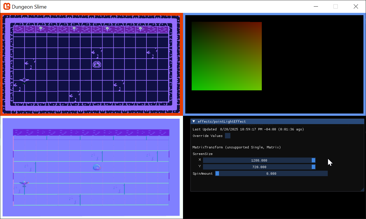
Figure 8-21: The point light can access screen space Note
The
LightBufferis showing that red/greenish color gradient because we forced the shader to return theinput.ScreenCoordinates.xy. This is only to verify that theScreenCoordinatesare working as expected.Now, the
pointLightEffectcan use the screen space coordinates to sample theNormalBuffervalues. To build intuition, start by just returning the values from theNormalBuffer.Start by updating the
MainPSin thepointLightEffectshader to read the values from theNormalBuffertexture, and then return immediately:float4 MainPS(LightVertexShaderOutput input) : COLOR { // correct the perspective divide. input.ScreenData /= input.ScreenData.z; // put the clip-space coordinates into screen space. float2 screenCoords = .5*(input.ScreenData.xy + 1); screenCoords.y = 1 - screenCoords.y; float4 normal = tex2D(NormalBufferSampler, screenCoords); return normal; }Strangely, this will return a
whitebox, instead of the normal data as expected; this happens because of a misunderstanding between the shader compiler andSpriteBatch.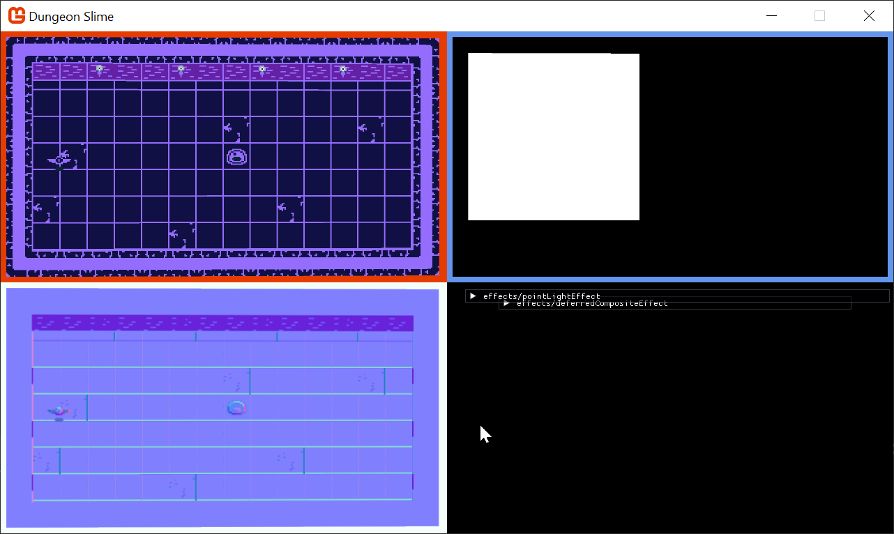
Figure 8-22: A white box instead of the normal data? Most of the time when
SpriteBatchis being used, there is a singleTextureandSamplerbeing used to draw a sprite to the screen. TheSpriteBatch's draw function passes the givenTexture2Dto the shader by setting it in theGraphicsDevice.Texturesarray directly. The texture is not being passed by name, it is being passed by index. In the lighting case, theSpriteBatchis being drawn with theCore.Pixeltexture (a white 1x1 image we generated in the earlier chapters).However, the shader compiler will aggressively optimize away data that is not being used in the shader. The current
pointLightEffect.fxdoes not use the default texture or sampler thatSpriteBatchexpects by default. The default texture is removed from the shader during compilation, because it is not used anywhere and has no effect. The only texture that is left is theNormalBuffer, which now becomes the first indexable texture.Despite passing the
NormalBuffertexture to the namedNormalTextureTexture2Dparameter in the shader before callingSpriteBatch.Draw(), theSpriteBatchcode itself then overwrites whatever is in texture slot0with the texture passed to theDraw()call, the white pixel.There are two workarounds:
Modify the shader code to read data from the main
SpriteTextureSamplerand use the resulting color "somehow" in the computation for the final result of the shader.The better approach is to pass the
NormalBufferto theDraw()function directly, and not bother sending it as a shader parameter at all.
Note
For example, You could multiply the color by a very small constant, like
.00001, and then add the product to the final color. It would have no perceivable effect, but the shader compiler would not be able to optimize the sampler away. However, this is useless and silly work. Worse, it will likely confuse anyone who looks at the shader in the future.Change the
Draw()method in thePointLightclass to pass thenormalBufferto theSpriteBatch.Draw()method instead of passing it in as a parameter to thePointLightMaterial.Here is the updated
Draw()method:public static void Draw(SpriteBatch spriteBatch, List<PointLight> pointLights, Texture2D normalBuffer) { spriteBatch.Begin( effect: Core.PointLightMaterial.Effect, blendState: BlendState.Additive ); foreach (var light in pointLights) { var diameter = light.Radius * 2; var rect = new Rectangle((int)(light.Position.X - light.Radius), (int)(light.Position.Y - light.Radius), diameter, diameter); spriteBatch.Draw(normalBuffer, rect, light.Color); } spriteBatch.End(); }And now the normal map is being rendered where the light exists.
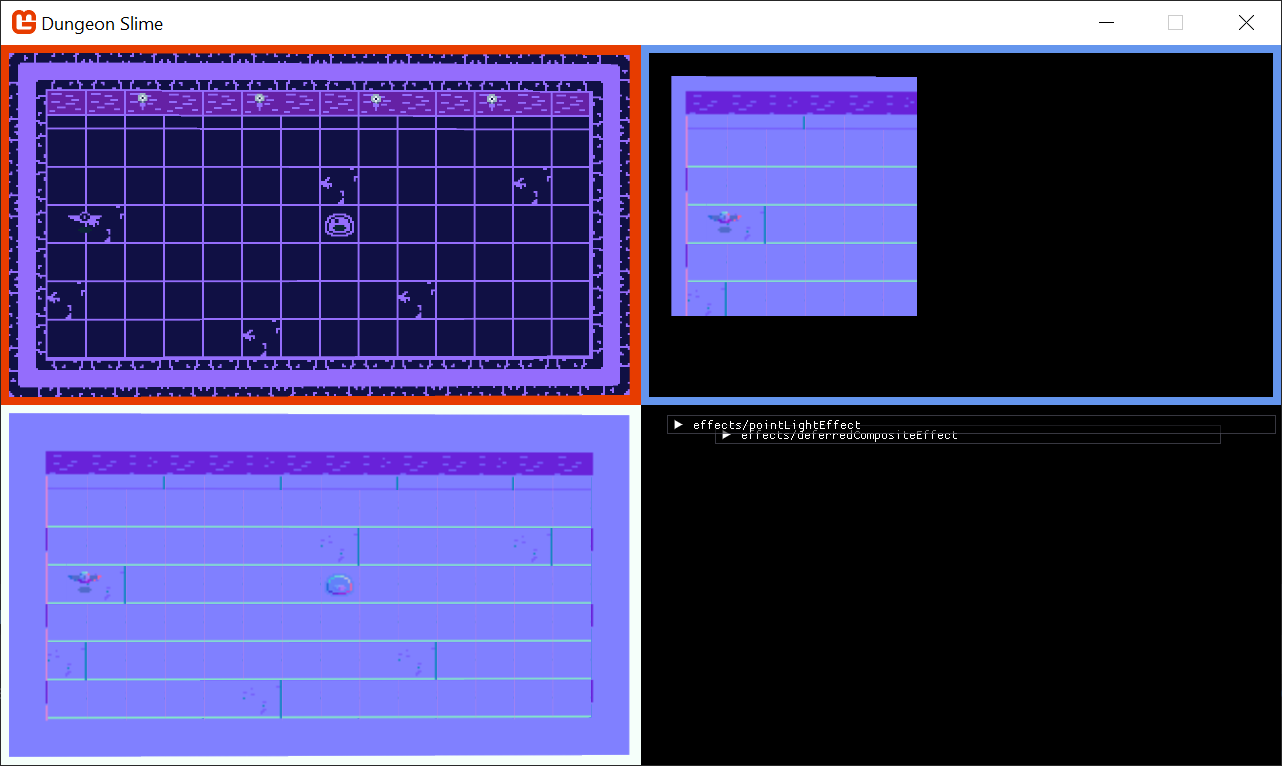
Figure 8-23: The light shows the normal map entirely Now it is time to use the normal data in conjunction with the light direction to decide how much light each pixel should receive.
Replace the
MainPSfunction in thepointLightEffectshader code with the following:float4 MainPS(LightVertexShaderOutput input) : COLOR { float dist = length(input.TextureCoordinates - .5); float range = 5; // arbitrary maximum. float falloff = saturate(.5 - dist) * (LightBrightness * range + 1); falloff = pow(abs(falloff), LightSharpness * range + 1); // correct the perspective divide. input.ScreenData /= input.ScreenData.z; // put the clip-space coordinates into screen space. float2 screenCoords = .5*(input.ScreenData.xy + 1); screenCoords.y = 1 - screenCoords.y; float4 normal = tex2D(NormalBufferSampler,screenCoords); // flip the y of the normals, because the art assets have them backwards. normal.y = 1 - normal.y; // convert from [0,1] to [-1,1] float3 normalDir = (normal.xyz-.5)*2; // find the direction the light is travelling at the current pixel float3 lightDir = float3(normalize(.5 - input.TextureCoordinates), 1); // how much is the normal direction pointing towards the light direction? float lightAmount = (dot(normalDir, lightDir)); float4 color = input.Color; color.a *= falloff * lightAmount; return color; }Note
The
normalDir,lightDir, anddotproduct are a simplified version of the Blinn-Phong shading model.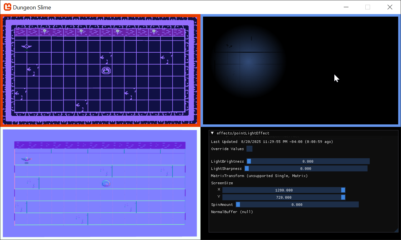
Figure 8-24: The light with the normal
To drive the effect for a moment, this gif shows the normal effect being blended in. Notice how the wings on the bat shade differently based on their position towards the light as the normal effect is brought in. (I added a test property to alter the normal strength just for observation to demonstrate)
| Figure 8-25: The lighting on the bat with normals |
The effect can be very subtle. To help illustrate it, here is a side by side comparison of the bat with the light moving around it in a circle. The ambient background light has been completely disabled. On the left, there is no normal mapping so the bat feels "flat". On the right, normal mapping is enabled, and the bat feels "lit" by the light.
| Figure 8-26: No normals enabled | Figure 8-27: Normals enabled |
Tone Mapping
The lights look good, but if we want them to really shine, we should add some tone mapping. Tone mapping is a broad term for a set of techniques that modify your color space for some desired effect. In Chapter 6, we explored various ways to dynamically modify colors. Now that we have lights in our game, I want the lights to really add contrast to the game. Areas where there is light should really feel "lit", and areas without light should feel "dark".
All of our lights add color to certain areas of the game window. We could write an equation that increases the color of any pixel when the pixel value is "colorful", and conversely, decreases the color of the pixel when the pixel's value is "not colorful".
The term, "colorful", can be expressed as a term called perceived brightness (Y), which we can compute with the formula,
Y = (light.r * .299) + (light.g * .587) + (light.b * .114)
That formula can be re-written using the dot product,
Y = dot(light, float3(.299, .587, .114))
Note
Where do those magic numbers come from?
Where did the .299, .587, and .114 come from? The ultra keen observer will notice that those values are shockingly close to the values we used to calculate the grayscale color back in Chapter 24 of the Building 2D Games Series. Recall that we produced the grayscale color like this:
// Calculate the grayscale value based on human perception of colors
float grayscale = dot(color.rgb, float3(0.3, 0.59, 0.11));
So where did those values come from? As discussed in Chapter 24, the values come from lots of experiments ran in laboratories where humans ranked perceived color brightness values. Now, those coefficients are a standard in the computer graphics industry.
Our goal is to exaggerate the final light values by modifying every pixel's color by the Y (perceived brightness) of that pixel. The following expression modifies the light's color by the Y value.
float3 toneMapped = light.xyz / (.5 + dot(light.xyz, float3(0.299, 0.587, 0.114)));
For visualization, make these adjustments to the deferredCompositeEffect.fx file:
float ToneMapLerp;
float AmbientLight;

float4 MainPS(VertexShaderOutput input) : COLOR
{
    float4 color = tex2D(SpriteTextureSampler,input.TextureCoordinates) * input.Color;
    float4 light = tex2D(LightBufferSampler,input.TextureCoordinates) * input.Color;

    float3 toneMapped = light.xyz / (.5 + dot(light.xyz, float3(0.299, 0.587, 0.114)));
    light.xyz = lerp(light.xyz, toneMapped, ToneMapLerp);

    light = saturate(light + AmbientLight);

    return color * light;
}
Note
If you want to do this yourself, remember to enable the deferredCompositeEffect.fx's debug UI by enabling the IsDebugVisible property in the Core's LoadContent() method:
DeferredCompositeMaterial.IsDebugVisible = true;
As you increase the ToneMapLerp variable, you can see how the light colors are enhanced.
| Figure 8-28: Subtle tone mapping |
Finally, it is not worth having the tone mapping controlled by a special shader parameter (it was just helpful for visualization). Remove the shader property and hardcode the value. Your deferredCompositeEffect.fx's MainPS() should look like this:
float AmbientLight;

float4 MainPS(VertexShaderOutput input) : COLOR
{
    float4 color = tex2D(SpriteTextureSampler,input.TextureCoordinates) * input.Color;
    float4 light = tex2D(LightBufferSampler,input.TextureCoordinates) * input.Color;

    float3 toneMapped = light.xyz / (.5 + dot(light.xyz, float3(0.299, 0.587, 0.114)));
    light.xyz = toneMapped;

    light = saturate(light + AmbientLight);

    return color * light;
}
Gameplay
Now that we have lights rendering in the game, it is time to hook a few more up in the game. There should be a light positioned next to each torch along the upper wall, and maybe a few lights that wander around the level.
Create a function in the
GameScenethat will initialize all of the lights. Feel free to add more:private void InitializeLights() { // torch 1 _lights.Add(new PointLight { Position = new Vector2(260, 100), Color = Color.CornflowerBlue, Radius = 500 }); // torch 2 _lights.Add(new PointLight { Position = new Vector2(520, 100), Color = Color.CornflowerBlue, Radius = 500 }); // torch 3 _lights.Add(new PointLight { Position = new Vector2(740, 100), Color = Color.CornflowerBlue, Radius = 500 }); // torch 4 _lights.Add(new PointLight { Position = new Vector2(1000, 100), Color = Color.CornflowerBlue, Radius = 500 }); // random lights _lights.Add(new PointLight { Position = new Vector2(Random.Shared.Next(50, 400),400), Color = Color.MonoGameOrange, Radius = 500 }); _lights.Add(new PointLight { Position = new Vector2(Random.Shared.Next(650, 1200),300), Color = Color.MonoGameOrange, Radius = 500 }); }Then replace the original code that created a single light with a call to the new
InitializeLightsmethod:public override void Initialize() { // ... // Replace this..... // _lights.Add(new PointLight // { // Position = new Vector2(300, 300), // Color = Color.CornflowerBlue // }); // With this new call to initialize lights for the scene InitializeLights(); }Given that the lights have a dynamic nature to them with the normal maps, it would be good to move some of them around.
Add this function to the
GameScene:private void MoveLightsAround(GameTime gameTime) { var t = (float)gameTime.TotalGameTime.TotalSeconds * .25f; var bounds = Core.GraphicsDevice.Viewport.Bounds; bounds.Inflate(-100, -100); var halfWidth = bounds.Width / 2; var halfHeight = bounds.Height / 2; var center = new Vector2(halfWidth, halfHeight); _lights[^1].Position = center + new Vector2(halfWidth * MathF.Cos(t), .7f * halfHeight * MathF.Sin(t * 1.1f)); _lights[^2].Position = center + new Vector2(halfWidth * MathF.Cos(t + MathHelper.Pi), halfHeight * MathF.Sin(t - MathHelper.Pi)); }And call it from the
Update()method:public override void Update(GameTime gameTime) { // ... // Move some lights around for artistic effect MoveLightsAround(gameTime); }
And now when the game runs, it looks like this.
Note
Make sure you also turn off the _deferredRenderer.DebugDraw call in the Draw method in GameScene, and the IsDebugVisible for the materials. It is useful for debugging shaders but kind of gets in the way of gameplay!
| Figure 8-29: The final results |
Conclusion
In this chapter, you accomplished the following:
- Learned the theory behind deferred rendering.
- Set up a rendering pipeline with multiple render targets (G-buffers) for color and normals.
- Created a point light shader.
- Used normal maps to allow 2D sprites to react to light as if they had 3D depth.
- Wrote a final composite shader to combine all the buffers into the final lit scene.
Our world is so much more atmospheric now, but there is one key ingredient missing... shadows! In our next and final effects chapter, we will bring our lights to life by making them cast dynamic shadows.
You can find the complete code sample for this chapter - here.
Continue to the next chapter, Chapter 09: Shadows Effect