Chapter 07: Sprite Vertex Shaders
Learn about vertex shaders and how to use them on sprites
Every shader has two main parts: the pixel shader, which we have been using to change the colors of our sprites, and the vertex shader. The vertex shader runs first, and its job is to determine the final shape and position of our geometry. Up until now, we have been using MonoGame's default vertex shader, which just draws our sprites as flat 2D rectangles.
In this chapter, we are going to unlock the power of the vertex shader. We will write our own custom vertex shader from scratch, which will allow us to break out of the 2D plane. We will learn how to use a perspective projection to give our flat world a cool, dynamic 3D feel.
At the end of this chapter, we will be able to make our sprites appear with 3d perspective.
| Figure 7-1: The main menu will have a 3d-esque title | Figure 7-2: The game will have a 3d-esque world |
If you are following along with code, here is the code from the end of the previous chapter.
Sample Source
The full source for this tuturial can be located on the 3.8.5 branch of the main MonoGame.Samples repository
As shown below:
https://github.com/MonoGame/MonoGame.Samples/tree/3.8.5/Tutorials/2dShaders
Default Vertex Shader
So far in this series, we have only dealt with pixel shaders. To recap, the job of a pixel shader is to convert some input (u,v) coordinate into an output color (r,g,b,a) value.
There has been a second shader function running all along behind the scenes, called the vertex shader. The vertex shader runs before the pixel shader whose job is to convert world-space vertex data into clip-space vertex data. Technically every call in MonoGame that draws data to the screen must provide a vertex shader function and a pixel shader function. However, the SpriteBatch class has a default implementation of the vertex shader that runs automatically.
The default SpriteBatch vertex shader takes the vertices that make up the sprite's corners, and applies an orthographic projection. The orthographic projection creates a 2d (flat) effect where shapes have no perspective, even when they are closer or further away from the origin.
The vertex shader that is being used can be found here, and is detailed below:
// ...

float4x4 MatrixTransform    _vs(c0) _cb(c0);

// ...

struct VSOutput
{
    float4 position		: SV_Position;
    float4 color		: COLOR0;
    float2 texCoord		: TEXCOORD0;
};

VSOutput SpriteVertexShader(	float4 position	: POSITION0,
                                float4 color	: COLOR0,
                                float2 texCoord	: TEXCOORD0)
{
    VSOutput output;
    output.position = mul(position, MatrixTransform);
    output.color = color;
    output.texCoord = texCoord;
    return output;
}
The SpriteVertexShader looks different from our pixel shaders in a few important ways,
- The inputs and outputs are different.
- The return type is not just a
float4, it is an entire struct,VSOutput, - The inputs are not the same as the pixel shader. The pixel shader got a
ColorandTextureCoordinates, but this vertex shader has aposition, acolor, and atexCoord.
- The return type is not just a
- There is a
MatrixTransformshader parameter available to this shader.
Input Semantics
The inputs to the vertex shader mirror the information that the SpriteBatchItem class bundles up for each vertex. If you look at the SpriteBatchItem, you will see that each sprite is made up of 4 VertexPositionColorTexture instances (one vertex/index for each corner):
public VertexPositionColorTexture vertexTL;
public VertexPositionColorTexture vertexTR;
public VertexPositionColorTexture vertexBL;
public VertexPositionColorTexture vertexBR;
Note
The SpriteBatchItem is part of the implementation of SpriteBatch, but SpriteBatchItem is not part of the public MonoGame API.
The VertexPositionColorTexture class is a standard MonoGame implementation of the IVertexType, and it defines a Position, a Color, and a TextureCoordinate for each vertex. These should look familiar, because they align with the inputs to the vertex shader function. The alignment is not happenstance, it is enforced by "semantics" that are applied to each field in the vertex.
Note
A VertexPositionColorTexture contains:
- A Vertex (corner)
- A Position (world-space coordinates)
- A Color
- A Texture
Just as the name states, you can check the other VertexDeclaration types in the API documentation for reference. You can always create your own custom declarations if any of the built in ones do not suffice, but you would not be able to use it with SpriteBatch by default.
This snippet from the VertexPositionColorTexture class defines the semantics for each field in the vertex by specifying the VertexElementUsage:
static VertexPositionColorTexture()
{
    var elements = new VertexElement[]
    {
        new VertexElement(0, VertexElementFormat.Vector3, VertexElementUsage.Position, 0),
        new VertexElement(12, VertexElementFormat.Color, VertexElementUsage.Color, 0),
        new VertexElement(16, VertexElementFormat.Vector2, VertexElementUsage.TextureCoordinate, 0)
    };
    VertexDeclaration = new VertexDeclaration(elements);
}
Tip
MonoGame is free and open source, so you can always go read the full source code for the VertexPositionColorTexture)
The vertex shader declares a semantic for each input using the : syntax:
// ...

VSOutput SpriteVertexShader(float4 position	: POSITION0,
                            float4 color	: COLOR0,
                            float2 texCoord	: TEXCOORD0)
{
    // ...
}

// ...
The semantics align with the values from the VertexElementUsage values. The table shows the correlation of the common semantics.
| Shader Semantic | VertexElementUsage Value |
|---|---|
POSITION |
VertexElementUsage.Position |
COLOR |
VertexElementUsage.Color |
TEXCOORD |
VertexElementUsage.TextureCoordinate |
These semantics are responsible for mapping the values written into the VertexPositionColorTexture to the corresponding inputs in the shader file.
Warning
The SpriteBatch class does not offer any way to change the vertex semantics that are passed to the vertex shader function.
Output Semantics
The same concept of semantics applies to the output of the shader. Here is the output type of the vertex shader function. Notice that the fields also have the : semantic syntax. These semantics instruct the graphics pipeline how to use the data:
struct VSOutput
{
    float4 position		: SV_Position;
    float4 color		: COLOR0;
    float2 texCoord		: TEXCOORD0;
};
This is the input struct for the standard pixel shaders from previous chapters. Notice how the fields are named slightly differently, but the semantics are identical:
struct VertexShaderOutput
{
   float4 Position : SV_POSITION;
   float4 Color : COLOR0;
   float2 TextureCoordinates : TEXCOORD0;
};
Tip
What is the difference between SV_Position and POSITION0 ?
In various places in the shader code, you may notice semantics using SV_Position and POSITION interchangeably. The SV_Position semantic is actually specific to Direct3D 10's System-Value Semantics. In fact, SV_Position is not a valid semantic in DesktopGL targets, so how can it be used interchangeably with POSITION?
MonoGame's default shader has a trick to re-map SV_Position to POSITION only when the target is OPENGL:
#if OPENGL
    #define SV_POSITION POSITION
    #define VS_SHADERMODEL vs_3_0
    #define PS_SHADERMODEL ps_3_0
#else
    #define VS_SHADERMODEL vs_4_0_level_9_1
    #define PS_SHADERMODEL ps_4_0_level_9_1
#endif
The #define line tells the shader parser to replace any instance of SV_POSITION with POSITION.
This implies that SV_POSITION is converted to POSITION when you are targetting OPENGL platforms, and left "as is" when targeting DirectX.
Matrix Transform
The default sprite vertex shader uses a mul() expression:
// ...

VSOutput SpriteVertexShader(	float4 position	: POSITION0,
                                float4 color	: COLOR0,
                                float2 texCoord	: TEXCOORD0)
{
    VSOutput output;
    output.position = mul(position, MatrixTransform);
    output.color = color;
    output.texCoord = texCoord;
    return output;
}

// ...
The reason this line exists is to convert the vertices from world-space to clip-space.
Tip
A vertex is a 3d coordinate in "world-space". But a monitor is a 2d display. Often, the screen's 2d coordinate system is called "clip-space". The vertex shader is converting the 3d world-space coordinate into a 2d clip-space coordinate. That conversion is a vector and matrix multiplication, using the MatrixTransform.
Read more about clip space on Wikipedia. We will cover more about how the conversion happens later in this chapter, in the perspective projection section.
The MatrixTransform is computed by the SpriteEffect class. The full source is available, here. The relevant lines are copied below:
// cache the shader parameter for the MatrixTransform
_matrixParam = Parameters["MatrixTransform"];

// ... some code left out for readability

// create a projection matrix in the _projection variable
Matrix.CreateOrthographicOffCenter(0, vp.Width, vp.Height, 0, 0, -1, out _projection);

// ... some code left out for readability

// assign the projection matrix to the MatrixTransform
_matrixParam.SetValue(_projection);
There are two common types of projection matrices,
- Orthographic (The default used by
SpriteBatch), - Perspective
The orthographic projection matrix produces the classic 2d sprite effect, where sprites have no perspective when they are on the sides of the screen.
Tip
Read more about these projection matrixes on MonoGame's Camera Article.
Along with many other "How To" and "What Is" articles explaining MonoGame architecture.
Custom Vertex Shader
Now that you understand the default vertex shader being used by SpriteBatch, we can replace the shader with a custom shader. The new shader must accomplish the basic requirements,
- convert the vertices from world-space to clip-space
- provide the input semantics required for the pixel shader.
To experiment with this, create a new Sprite Effect called 3dEffect in the MonoGameLibrary's shared content effects folder.
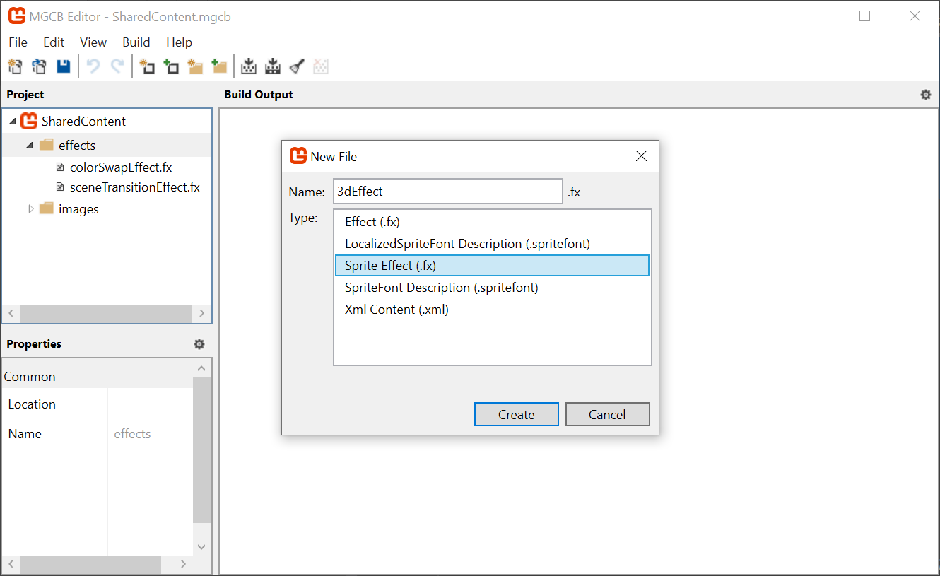 |
|---|
Figure 7-3: Adding the 3dEffect to MGCB |
Follow along with the steps to set up the effect.
We need to add a vertex shader function. To do that, we need to add a new
structthat holds all the input semantics passed fromSpriteBatch:struct VertexShaderInput { float4 Position : POSITION0; float4 Color : COLOR0; float2 TexCoord : TEXCOORD0; };Tip
Use a struct for inputs and outputs.
The default vertex shader accepts all 3 inputs (
position,color, andtexCoord) as direct parameters. However, when you have more than 1 semantic, it is helpful to organize all of the inputs in astruct, it is simply best practice and avoids common mistakes with "magic numbers" or "random variables".If you look through other shaders, you may see shader functions using individual parameters which works, but it is not a good practice.
Now add the stub for the vertex shader function:
VertexShaderOutput MainVS(VertexShaderInput input)
{
    VertexShaderOutput output;

    return output;
}
Warning
Constructs and parameters MUST appear or be defined BEFORE they are used, so if you add the above function BEFORE the struct for the
VertexShaderOutput, the struct will not be recognized.So be sure to place the function AFTER the struct and it will work as intended.
Now, modify the
techniqueto include the vertex shader function. Until now, theMainVS()function is just considered as any average function in your shader, and because it was not used by theMainPSpixel shader, it would be compiled out of the shader.Important
When you specify the
MainVS()vertex shader function, you are overriding the defaultSpriteBatchvertex shader function:technique SpriteDrawing { pass P0 { PixelShader = compile PS_SHADERMODEL MainPS(); VertexShader = compile VS_SHADERMODEL MainVS(); } };The shader will not compile yet, because the
VertexShaderOutputhas not been completely initialized. We need to replicate theMatrixTransformstep to convert the vertices from world-space to clip-space. Add theMatrixTransformshader parameter:// ... float4x4 MatrixTransform; // ...And then assign all of the output semantics in the vertex shader, replacing the
MainVSstub we added earlier:VertexShaderOutput MainVS(VertexShaderInput input) { VertexShaderOutput output; output.Position = mul(input.Position, MatrixTransform); output.Color = input.Color; output.TextureCoordinates = input.TexCoord; return output; }To validate this is working, we should try to use the new effect. For now, we will experiment in the
TitleSceneclass in theDungeonSlimeproject. Create a class member for the newMaterial:// The 3d material private Material _3dMaterial;Load the shader using the hot reload system in the
LoadContentmethod:// Load the 3d effect _3dMaterial = Core.SharedContent.WatchMaterial("effects/3dEffect");Add the using statement to the
MonoGame.Contentnamespace at the top of the class, to access where theWatchMaterialextension is defined:using MonoGameLibrary.Content;Make sure to enable the hot-reload for the shader by adding this to the
Updatemethod:// Enable hot reload _3dMaterial.Update();Then, in the
Drawmethod, use the effect when drawing the title text:// Begin the sprite batch to prepare for rendering. Core.SpriteBatch.Begin( samplerState: SamplerState.PointClamp, effect: _3dMaterial.Effect);When the game runs, the text will be missing because we never created a projection matrix to assign to the
MatrixTransformshader parameter for the new effect (remember, we are overriding the defaultSpriteBatchbehaviour with our own implementation).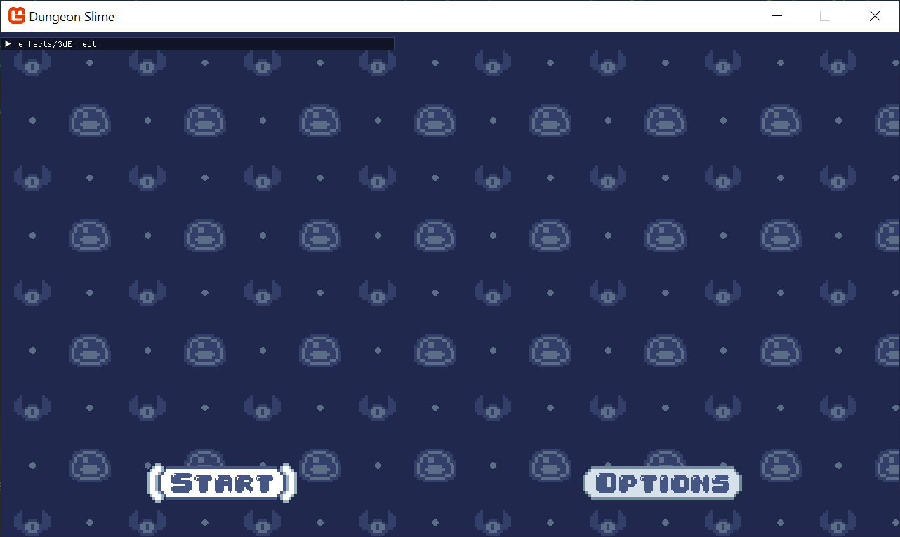
Figure 7-4: The main menu title is missing Note
If you still see the Title text but not the background, go back and check, you replaced the WRONG
SpriteBatch.Begincall.Replace the original
_3dMaterialparameter initialization with the following code when loading the material in theLoadContentmethod:// Load the 3d effect _3dMaterial = Core.SharedContent.WatchMaterial("effects/3dEffect"); _3dMaterial.IsDebugVisible = true; // this matrix code is taken from the default vertex shader code. Matrix.CreateOrthographicOffCenter( left: 0, right: Core.GraphicsDevice.Viewport.Width, bottom: Core.GraphicsDevice.Viewport.Height, top: 0, zNearPlane: 0, zFarPlane: -1, out var projection); _3dMaterial.SetParameter("MatrixTransform", projection);And now you should see the text normally again.
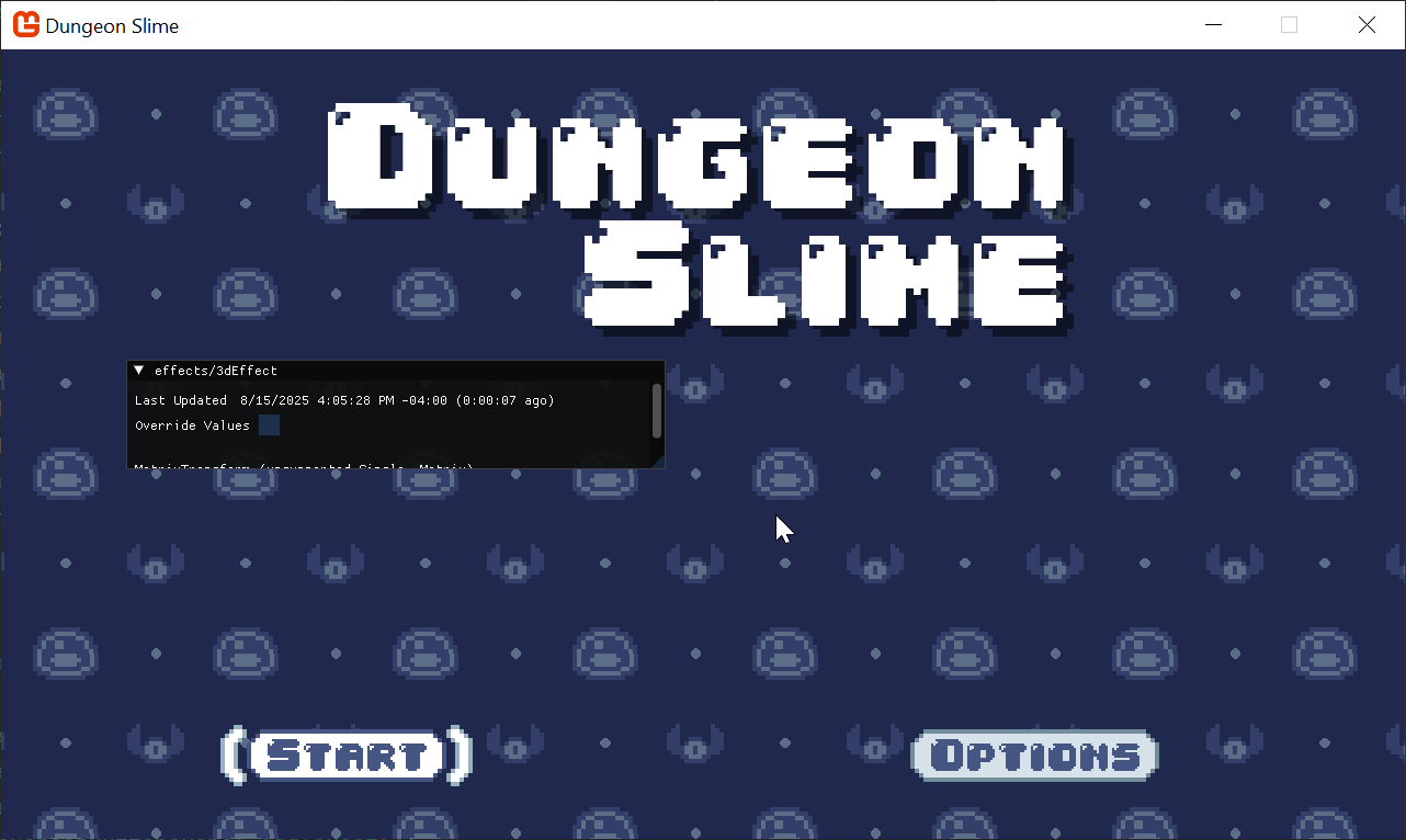 |
|---|
| Figure 7-5: The main menu, but rendered with a custom vertex shader |
Making it Move
As a quick experiment, we can show that the vertex shader can indeed modify the vertex positions further if we want to. For now, add a temporary shader parameter called DebugOffset in the 3dEffect.fx shader:
// ...

float2 DebugOffset;

// ...
And change the vertex shader (MainVS), add the DebugOffset to the output.Position after the clip-space conversion:
// ...

VertexShaderOutput MainVS(VertexShaderInput input)
{
    VertexShaderOutput output;
    output.Position = mul(input.Position, MatrixTransform);
    output.Position.xy += DebugOffset;
    output.Color = input.Color;
    output.TextureCoordinates = input.TexCoord;
    return output;
}

// ...
The sprites now move around as we adjust the shader parameter values.
| Figure 7-6: We can control the vertex positions |
It is important to build intuition for the different coordinate systems involved. Instead of adding the DebugOffset after the clip-space conversion, if you try to add it before, like in the code below:
// ...

VertexShaderOutput MainVS(VertexShaderInput input)
{
    VertexShaderOutput output;
    float4 pos = input.Position;
    pos.xy += DebugOffset;
    output.Position = mul(pos, MatrixTransform);
    output.Color = input.Color;
    output.TextureCoordinates = input.TexCoord;
    return output;
}

// ...
Then you will not see much movement at all. This is because the DebugOffset values only go from 0 to 1, and in world space, this really only amounts to a single pixel. In fact, exactly how much an addition of 1 happens to make is entirely defined by the conversion to clip-space. The projection matrix we created treats world space coordinates with an origin around the screen's center, where 1 unit maps to 1 pixel.
Note
Sometimes this is exactly what you want, and sometimes it can be just confusing. The important thing to remember is which coordinate space you are doing your math in.
| Figure 7-7: Changing coordinates before clip-space conversion |
Perspective Projection
The world-space vertices can have their x and y values modified in the vertex shader, but what about the z component? The orthographic projection essentially ignores the z component of a vertex and treats all vertices as though they are an equal distance away from the camera. If you change the z value, you may expect the sprite to appear closer or further away from the camera, but the orthographic projection matrix prevents that from happening.
To check, try to modify the shader code to adjust the z value based on one of the debug values:
// ...

VertexShaderOutput MainVS(VertexShaderInput input)
{
    VertexShaderOutput output;
    float4 pos = input.Position;
    pos.z -= DebugOffset.x;
    output.Position = mul(pos, MatrixTransform);
    output.Color = input.Color;
    output.TextureCoordinates = input.TexCoord;
    return output;
}

// ...
Tip
Near and Far plane clipping.
Keep in mind that if you modify the z value too much, it will likely step outside of the near and far planes of the orthographic projection matrix. If this happens, the sprite will vanish, because the projection matrix does not handle coordinates outside of the near and far planes. The value must be between the near and far plane of the matrix we created a few steps ago. We set the values in the CreateOrthographicOffCenter() function to 0 and 1.
zNearPlane: 0, zFarPlane: -1
Nothing happens!
To fix this, we need to use a perspective projection matrix instead of an orthographic projection matrix. MonoGame has a built in method called Matrix.CreatePerspectiveFieldOfView() that will do most of the heavy lifting for us. Once we have a perspective matrix, it would also be helpful to control where the camera is looking. The math is easy, but it would be helpful to put it in a new helper class.
Create a new file in the MonoGameLibrary's graphics folder called
SpriteCamera3d.cs, and paste the following code. We are going to skip over the math internals:using System; using Microsoft.Xna.Framework; namespace MonoGameLibrary.Graphics; public class SpriteCamera3d { /// <summary> /// The field of view for the camera. /// </summary> public int Fov { get; set; } = 120; /// <summary> /// By default, the camera is looking at the center of the screen. /// This offset value can be used to "turn" the camera from the center towards the given vector value. /// </summary> public Vector2 LookOffset { get; set; } = Vector2.Zero; /// <summary> /// Produce a matrix that will transform world-space coordinates into clip-space coordinates. /// </summary> /// <returns></returns> public Matrix CalculateMatrixTransform() { var viewport = Core.GraphicsDevice.Viewport; // start by creating the projection matrix var projection = Matrix.CreatePerspectiveFieldOfView( fieldOfView: MathHelper.ToRadians(Fov), aspectRatio: Core.GraphicsDevice.Viewport.AspectRatio, nearPlaneDistance: 0.0001f, farPlaneDistance: 10000f ); // position the camera far enough away to see the entire contents of the screen var cameraZ = (viewport.Height * 0.5f) / (float)Math.Tan(MathHelper.ToRadians(Fov) * 0.5f); // create a view that is centered on the screen var center = .5f * new Vector2(viewport.Width, viewport.Height); var look = center + LookOffset; var view = Matrix.CreateLookAt( cameraPosition: new Vector3(center.X, center.Y, -cameraZ), cameraTarget: new Vector3(look.X, look.Y, 0), cameraUpVector: Vector3.Down ); // the standard matrix format is world*view*projection, // but given that we are skipping the world matrix, its just view*projection return view * projection; } }Now, instead of creating an orthographic matrix in the
TitleScene, we can use the new class (getting rid of the old dustyCreateOrthographicOffCenterfunction):public override void LoadContent() { // ... // Load the 3d effect _3dMaterial = Core.SharedContent.WatchMaterial("effects/3dEffect"); _3dMaterial.IsDebugVisible = true; var camera = new SpriteCamera3d(); _3dMaterial.SetParameter("MatrixTransform", camera.CalculateMatrixTransform()); }Moving the
zvalue uniformly in the shader will not be visually stimulating. A more impressive demonstration of the perspective projection would be to rotate the vertices around the center of the sprite, back in the3dEffect.fxshader, replace theMainVSfunction with the following:VertexShaderOutput MainVS(VertexShaderInput input) { VertexShaderOutput output; float4 pos = input.Position; // hardcode the screen-size for now. float2 screenSize = float2(1280, 720); // create the center of rotation float2 centerXZ = float2(screenSize.x * .5, 0); // convert the debug variable into an angle from 0 to 2 pi. // shaders use radians for angles, so 2 pi = 360 degrees float angle = DebugOffset.x * 6.28; // pre-compute the cos and sin of the angle float cosA = cos(angle); float sinA = sin(angle); // shift the position to the center of rotation pos.xz -= centerXZ; // compute the rotation float nextX = pos.x * cosA - pos.z * sinA; float nextZ = pos.x * sinA + pos.z * cosA; // apply the rotation pos.x = nextX; pos.z = nextZ; // shift the position away from the center of rotation pos.xz += centerXZ; output.Position = mul(pos, MatrixTransform); output.Color = input.Color; output.TextureCoordinates = input.TexCoord; return output; }
And now when the debug X parameter is adjusted (y does nothing at this point), the text spins in a way that was not possible with the default SpriteBatch vertex shader.
| Figure 7-8: A spinning text |
The text disappears for half of the rotation. That happens because as the vertices are rotated, the triangle itself started to point away from the camera. By default, SpriteBatch will cull (remove) any faces that point away from the camera.
Change the rasterizerState to CullNone when beginning the sprite batch of the TitleScreen's Draw method:
// Begin the sprite batch to prepare for rendering.
Core.SpriteBatch.Begin(
    samplerState: SamplerState.PointClamp,
    rasterizerState: RasterizerState.CullNone,
    effect: _3dMaterial.Effect);
And voilà, the text no longer disappears on its flip side.
| Figure 7-9: A spinning text with reverse sides |
Note
What is Culling?
The term, "Culling", is used to describe a scenario when some triangles are not drawn due to some sort of optimization. There are many types of culling, but in this case, we are discussing a specific type of optimization called "Back-face Culling". Learn more about it on wikipedia.
You may find that the field of view is too high for your taste. Try lowering the field of view to 60 (in the SpriteCamera3d.cs properties), and you will see something similar to this,
| Figure 7-10: A spinning text with reverse sides with smaller fov |
As a final touch, we should remove the hard-coded screenSize variable from the shader, and extract it as a shader parameter. While we are at it, clean up and remove the debug parameters as well.
Remove the old hardcoded/debug variables from the
3dEffect.fxshader:// ... float2 DebugOffset; // remove this line // ... VertexShaderOutput MainVS(VertexShaderInput input) { // ... // hardcode the screen-size for now. float2 screenSize = float2(1280, 720); // remove this line (and comment) // ... }Add the following two parameters so we can do things more dynamically:
// ...

float2 ScreenSize;
float SpinAmount;

// ...
Update the
MainVSfunction to utilize the two new shader parameters:VertexShaderOutput MainVS(VertexShaderInput input) { VertexShaderOutput output; float4 pos = input.Position; // create the center of rotation float2 centerXZ = float2(ScreenSize.x * .5, 0); // convert the debug variable into an angle from 0 to 2 pi. // shaders use radians for angles, so 2 pi = 360 degrees float angle = SpinAmount * 6.28; // ... }Then back in the
TitleScreen.csLoadContentmethod, make sure to set the newScreenSizeparameter correctly from C#:var camera = new SpriteCamera3d(); _3dMaterial.SetParameter("MatrixTransform", camera.CalculateMatrixTransform()); _3dMaterial.SetParameter("ScreenSize", new Vector2(Core.GraphicsDevice.Viewport.Width, Core.GraphicsDevice.Viewport.Height));And instead of manually controlling the spin angle, we can make the title spin gentle following the mouse position. In the
Update()function, add the following snippet:public override void Update(GameTime gameTime) { _3dMaterial.Update(); var spinAmount = Core.Input.Mouse.X / (float)Core.GraphicsDevice.Viewport.Width; spinAmount = MathHelper.SmoothStep(-.1f, .1f, spinAmount); _3dMaterial.SetParameter("SpinAmount", spinAmount); // ... }
| Figure 7-11: Spin controlled by the mouse |
Now when ever you move your Mouse left to right, the title will spin accordingly.
Applying it to the Game
It was helpful to use the TitleScene to build intuition for the vertex shader, but now it is time to apply the perspective vertex shader to the game itself to add immersion and a sense of depth to the gameplay. The goal is to use the same effect in the GameScene.
Making One Big Shader
A problem emerges right away. The GameScene is already using the color swapping effect to draw the sprites, and SpriteBatch can only use a single shader per batch.
To solve this problem, we will collapse our shaders into a single shader that does it all the effects, the color swapping, greyscale and the vertex manipulation. Writing code to be re-usable is a challenge for all programming languages, and shader languages are no different.
Note
The Uber Shader
Sometimes when people collapse lots of shaders into a single shader, it is called an "Uber" shader. For Dungeon Slime, that term is premature, but the spirit is the same. Finding ways to collapse code into simpler code pathways is helpful for keeping your code easy to understand, but it can also keep your shader's compilation times faster, and runtime performance higher.
For an insightful read, check out this article on shader permutations.
MonoGame shaders can reference code from multiple files by using the #include syntax. MonoGame itself uses this technique itself in the default vertex shader for SpriteBatch. We can move some of the code from our existing .fx files into a new .fxh file, re-write the existing shaders to #include the new .fxh file, and then be able to write additional .fx files that #include multiple of our files and compose the functions into a single effect.
Tip
.fxh vs .fx.
.fxh is purely convention. Technically you can use whatever file extension you want, but .fxh implies the usage of the file is for shared code, and does not contain a standalone effect itself. The h is simply referred to as a header file.
Follow the steps below to refactor the shader code, and to use the #include syntax for referring to the new .fxh files.
Before we get started, we are going to be editing
.fxhfiles, so it would be nice if the hot-reload system also listened to these.fxhfile changes. Update theWatchconfiguration in theDungeonSlime.csprojfile to include the.fxhfile type:<ItemGroup Condition="'$(OnlyWatchContentFiles)'=='true'"> <!-- Adds .fx files to the `dotnet watch`'s file scope --> <Watch Include="../**/*.fx;../**/*.fxh" /> <!-- Removes the .cs files from `dotnet watch`'s compile scope --> <Compile Update="**/*.cs" Watch="false" /> </ItemGroup>Time to start factoring out some shared components into a few different
.fxhfiles.Create a file in the MonoGameLibrary's
SharedContent/effectsfolder calledcommon.fxh.Tip
.fxhfiles do not need to be added to your MonoGame Content Project.This file will contain utilities that can be shared for all effects, such as the
structtypes that define the inputs and outputs of the vertex and pixel shaders:#ifndef COMMON #define COMMON struct VertexShaderInput { float4 Position : POSITION0; float4 Color : COLOR0; float2 TexCoord : TEXCOORD0; }; struct VertexShaderOutput { float4 Position : SV_POSITION; float4 Color : COLOR0; float2 TextureCoordinates : TEXCOORD0; }; #endifTip
Include Guards.
The
#includesyntax is taking the referenced file and inserting it into the code. If the same file was included twice, then the contents that file would be written out as code twice. Defining astructor function this way would cause the compiler to fail, because thestructwould be declared twice, which is illegal.To work around this, a solution is to use a practice called "include guards", where the file itself defines a symbol (in the case above, the symbol is
COMMON). The file only compiles to anything if the symbol has not yet been defined. The#ifndefstands for "if not yet defined".Once the
COMMONsymbol is defined once, any future inclusions of the file will not match the#ifndefclause.Then, in the
3dEffect.fxfile, remove theVertexShaderInputandVertexShaderOutputstructs and replace them with this line:#include "common.fxh"Note
If you recall what was stated earlier about the processing order of the shader, the file is read in sequence, so the include MUST be defined BEFORE its contents are used. You can put it at the top of the file (like a using) but only if it does not interfere with the shader processing. There is no hard and fast rule, so just use common sense, if it does not compile or it errors, then you need to change it.
If you run the game, nothing should change, except that the shader code is more modular. To continue, create another header file next to the
3dEffect.fxshader called3dEffect.fxhin the same folder. Paste the contents:#ifndef EFFECT_3DEFFECT #define EFFECT_3DEFFECT #include "common.fxh" float4x4 MatrixTransform; float2 ScreenSize; float SpinAmount; VertexShaderOutput MainVS(VertexShaderInput input) { VertexShaderOutput output; float4 pos = input.Position; // create the center of rotation float2 centerXZ = float2(ScreenSize.x * .5, 0); // convert the debug variable into an angle from 0 to 2 pi. // shaders use radians for angles, so 2 pi = 360 degrees float angle = SpinAmount * 6.28; // pre-compute the cos and sin of the angle float cosA = cos(angle); float sinA = sin(angle); // shift the position to the center of rotation pos.xz -= centerXZ; // compute the rotation float nextX = pos.x * cosA - pos.z * sinA; float nextZ = pos.x * sinA + pos.z * cosA; // apply the rotation pos.x = nextX; pos.z = nextZ; // shift the position away from the center of rotation pos.xz += centerXZ; output.Position = mul(pos, MatrixTransform); output.Color = input.Color; output.TextureCoordinates = input.TexCoord; return output; } #endifNow in the
3dEffect.fx, instead of#include common.fxh, we can directly reference3dEffect.fxhinstead. We should also remove the code that was just pasted into the new common header file. Here is the slimmed down3dEffect.fxfile (much cleaner):#if OPENGL #define SV_POSITION POSITION #define VS_SHADERMODEL vs_3_0 #define PS_SHADERMODEL ps_3_0 #else #define VS_SHADERMODEL vs_4_0_level_9_1 #define PS_SHADERMODEL ps_4_0_level_9_1 #endif Texture2D SpriteTexture; sampler2D SpriteTextureSampler = sampler_state { Texture = <SpriteTexture>; }; #include "3dEffect.fxh" float4 MainPS(VertexShaderOutput input) : COLOR { return tex2D(SpriteTextureSampler,input.TextureCoordinates) * input.Color; } technique SpriteDrawing { pass P0 { PixelShader = compile PS_SHADERMODEL MainPS(); VertexShader = compile VS_SHADERMODEL MainVS(); } };It is time to do the same thing for the
colorSwapEffect.fxfile. The goal is to split the file apart into a header file that defines the components of the effect, and leave thefxfile itself without much implementation. Create a new file calledcolors.fxh, and paste the following:#ifndef COLORS #define COLORS #include "common.fxh" // the custom color map passed to the Material.SetParameter() Texture2D ColorMap; sampler2D ColorMapSampler = sampler_state { Texture = <ColorMap>; MinFilter = Point; MagFilter = Point; MipFilter = Point; AddressU = Clamp; AddressV = Clamp; }; // a control variable to lerp between original color and swapped color float OriginalAmount; float Saturation; float4 Grayscale(float4 color) { // Calculate the grayscale value based on human perception of colors float grayscale = dot(color.rgb, float3(0.3, 0.59, 0.11)); // create a grayscale color vector (same value for R, G, and B) float3 grayscaleColor = float3(grayscale, grayscale, grayscale); // Linear interpolation between the grayscale color and the original color's // rgb values based on the saturation parameter. float3 finalColor = lerp(grayscale, color.rgb, Saturation); // Return the final color with the original alpha value return float4(finalColor, color.a); } float4 SwapColors(float4 color) { // produce the key location // note the x-offset by half a texel solves rounding errors. float2 keyUv = float2(color.r , 0); // read the swap color value float4 swappedColor = tex2D(ColorMapSampler, keyUv) * color.a; // ignore the swap if the map does not have a value bool hasSwapColor = swappedColor.a > 0; if (!hasSwapColor) { return color; } // return the result color return lerp(swappedColor, color, OriginalAmount); } float4 ColorSwapPS(VertexShaderOutput input) : COLOR { // read the original color value float4 originalColor = tex2D(SpriteTextureSampler,input.TextureCoordinates); float4 swapped = SwapColors(originalColor); float4 saturated = Grayscale(swapped); return saturated; } #endifNote
Ignore any red squiggles in the editor, this header is not being written to run independently like the
3dEffect.fxhheader, it is just a code template to be used in the main shader. How you break up your shader code is always a preference.Then, the
colorSwapEffect.fxfile can be replaced with the following code:#if OPENGL #define SV_POSITION POSITION #define VS_SHADERMODEL vs_3_0 #define PS_SHADERMODEL ps_3_0 #else #define VS_SHADERMODEL vs_4_0_level_9_1 #define PS_SHADERMODEL ps_4_0_level_9_1 #endif // the main Sprite texture passed to SpriteBatch.Draw() Texture2D SpriteTexture; sampler2D SpriteTextureSampler = sampler_state { Texture = <SpriteTexture>; }; #include "colors.fxh" technique SpriteDrawing { pass P0 { PixelShader = compile PS_SHADERMODEL ColorSwapPS(); } };Now most of the components we would like to combine into a single effect have been split into various
.fxhheader files, but their relative location is CRUCIAL when refering to related functionality, to demonstrate this, we will "break" a shader and show how to fix it.Create a new "sprite effect" using the MGCB editor in the
_DungeonSlime_'s contenteffectsfolder calledgameEffect.fx, and simply add the following:#include "common.fxh"This refers to the previously created common header file, you should now see an error like this:
Warning
We have been adding a lot of files to the MonoGameLibrary, but this shader should go into the DungeonSlime project, because it is a game specific shader.
error PREPROCESS01: File not found: common.fxh in .(MonoGame.Effect.Preprocessor+MGFile)This happens because the
gameEffect.fxfile is in a different folder than thecommon.fxhfile, and the"common.fxh"is treated as a relative file path lookup. Instead, in thegameEffect.fxfile, use this line:#include "../../../MonoGameLibrary/SharedContent/effects/common.fxh"Note
You should see errors in the editor or when building the shader now because the
common.fxhalready contains theVertexShaderOutputstruct, hence the version ingameeffect.fxis now a duplicate.gameEffect.fxfile can also reference the other two.fxhfiles we just created, so now add the following additional includes:#include "../../../MonoGameLibrary/SharedContent/effects/3dEffect.fxh" #include "../../../MonoGameLibrary/SharedContent/effects/colors.fxh"Note
These replace the
common.fxhyou just added for test, as the other effect headers already referencecommon.fxh, even shaders have inheritance. You "could" still include it because thefxhfiles use the#ifndefcheck, meaning it will ignore duplicates, but why make it more complicated?And the only thing the
gameEffect.fxfile needs to specify is which functions to use for the vertex shader and pixel shader functions, so you can safely remove the rest (except for the#iftest):technique SpriteDrawing { pass P0 { VertexShader = compile VS_SHADERMODEL MainVS(); PixelShader = compile PS_SHADERMODEL ColorSwapPS(); } };To keep things simple, the entire contents of the
gameEffect.fxis shown below:#if OPENGL #define SV_POSITION POSITION #define VS_SHADERMODEL vs_3_0 #define PS_SHADERMODEL ps_3_0 #else #define VS_SHADERMODEL vs_4_0_level_9_1 #define PS_SHADERMODEL ps_4_0_level_9_1 #endif Texture2D SpriteTexture; sampler2D SpriteTextureSampler = sampler_state { Texture = <SpriteTexture>; }; #include "../../../MonoGameLibrary/SharedContent/effects/3dEffect.fxh" #include "../../../MonoGameLibrary/SharedContent/effects/colors.fxh" technique SpriteDrawing { pass P0 { VertexShader = compile VS_SHADERMODEL MainVS(); PixelShader = compile PS_SHADERMODEL ColorSwapPS(); } };To load it into the
GameScene, we need to delete the old class member for_colorSwapMaterial, and replace it with the following, adding aSpriteCamera3ddefinition as well:// The uber material for the game objects private Material _gameMaterial; private SpriteCamera3d _camera;Next, apply all of the parameters to the new single material in the
LoadContentmethod, replacing the_colorSwapMaterialand_colorMapsections as follows:public override void LoadContent() { // ... // Load the colorSwap map _colorMap = Content.Load<Texture2D>("images/color-map-dark-purple"); _slimeColorMap = new RedColorMap(); _slimeColorMap.SetColorsByExistingColorMap(_colorMap); _slimeColorMap.SetColorsByRedValue(new Dictionary<int, Color> { // main color [32] = Color.LightSteelBlue, }, false); // Load the game material _gameMaterial = Content.WatchMaterial("effects/gameEffect"); _gameMaterial.IsDebugVisible = true; _gameMaterial.SetParameter("ColorMap", _colorMap); _camera = new SpriteCamera3d(); _gameMaterial.SetParameter("MatrixTransform", _camera.CalculateMatrixTransform()); _gameMaterial.SetParameter("ScreenSize", new Vector2(Core.GraphicsDevice.Viewport.Width, Core.GraphicsDevice.Viewport.Height)); }In the
Updatemethod to also swap out the_colorSwapMaterial.Update()update call:// Update the colorSwap material if it was changed _gameMaterial.Update();Any remaining places where the old
_colorSwapMaterialis being referenced should be swapped to use the_gameMaterialinstead, including:- Update - 1 reference.
- Draw - 4 references.
Somewhat optionally, remember to add the
rasterizerState: RasterizerState.CullNoneto theSpriteBatch.Draw()call if you do not want the game to vanish when theSpinAmountgoes beyond half a rotation. In practice, we will not be be spinning the game world that much, so it does not really matter.
if you still have any old references to the
_grayscaleEffectmake sure to remove those as well as they are no longer used.
The code now compiles and everything runs, but we are not spinning yet, so let us update that show off the new feature.
Adjusting the Game
Now that the 3d effect can be applied to the game objects, it would be good to make the world tilt slightly towards the player character to give the movement more weight. Instead of spinning the entire map, an easier approach will be to modify the MatrixTransform that is being passed to the shader.
Add this snippet to the top of the GameScene's Update() method:
public override void Update(GameTime gameTime)
{
    // Ensure the UI is always updated
    _ui.Update(gameTime);

    // Set the camera view to look at the player slime
    var viewport = Core.GraphicsDevice.Viewport;
    var center = .5f * new Vector2(viewport.Width, viewport.Height);
    var slimePosition = new Vector2(_slime?.GetBounds().X ?? center.X, _slime?.GetBounds().Y ?? center.Y);
    var offset = .01f * (slimePosition - center);
    _camera.LookOffset = offset;
    _gameMaterial.SetParameter("MatrixTransform", _camera.CalculateMatrixTransform());

    // ...
}
Now the project should compile and give you the following effect, pretty cool!
| Figure 7-12: Camera follows the slime |
The clear color of the scene can be seen in the corners (the CornflowerBlue). Pick whatever clear color you think looks good for the color swapping:
public override void Draw(GameTime gameTime)
{
    // Clear the back buffer.
    Core.GraphicsDevice.Clear(new Color(32, 16, 20));

    // ...
}
And to finish this chapter, the game looks like this,
| Figure 7-13: vertex shaders make it pop |
Conclusion
Our game has a whole new dimension! In this chapter, you accomplished the following:
- Learned the difference between a vertex shader and a pixel shader.
- Wrote a custom vertex shader to override the
SpriteBatchdefault. - Replaced the default orthographic projection with a perspective projection to create a 3D effect.
- Refactored shader logic into modular
.fxhheader files for better organization. - Combined vertex and pixel shader effects into a single "uber shader".
The world feels much more alive now that it tilts and moves with the player. In the next chapter, we will build on this sense of depth by tackling a 2D dynamic lighting system.
You can find the complete code sample for this chapter - here.
Continue to the next chapter, Chapter 08: Light Effect